802.11ac Gated Power Measurements using NI-WLAN Toolkit
- Subscribe to RSS Feed
- Mark as New
- Mark as Read
- Bookmark
- Subscribe
- Printer Friendly Page
- Report to a Moderator
Products and Environment
This section reflects the products and operating system used to create the example.To download NI software, including the products shown below, visit ni.com/downloads.
- RF|Wireless
Hardware
- LabVIEW
Software
- NI RF Device Drivers
Driver
Code and Documents
Attachment
Overview
This example demonstrates how to measure the power of various fields within the WLAN frame (PPDU) of an 802.11ac waveform using the Gated Power Property Nodes in NI-WLAN Toolkit.
Description
NI-WLAN Generation Toolkit is used to generate a waveform containing an 802.11ac data packet. The NI-RFSG driver is used to create a generation session that transmits this waveform as a RF signal. The signal is received by an analysis session created by the NI-RFSA driver and analyzed by the NI-WLAN Analysis Toolkit. The example has been tested on the NI PXIe-5644R Vector Signal Transceiver. However, the user can use any vector signal analyzer/generator supported by the NI-RFSA and NI-RFSG drivers.
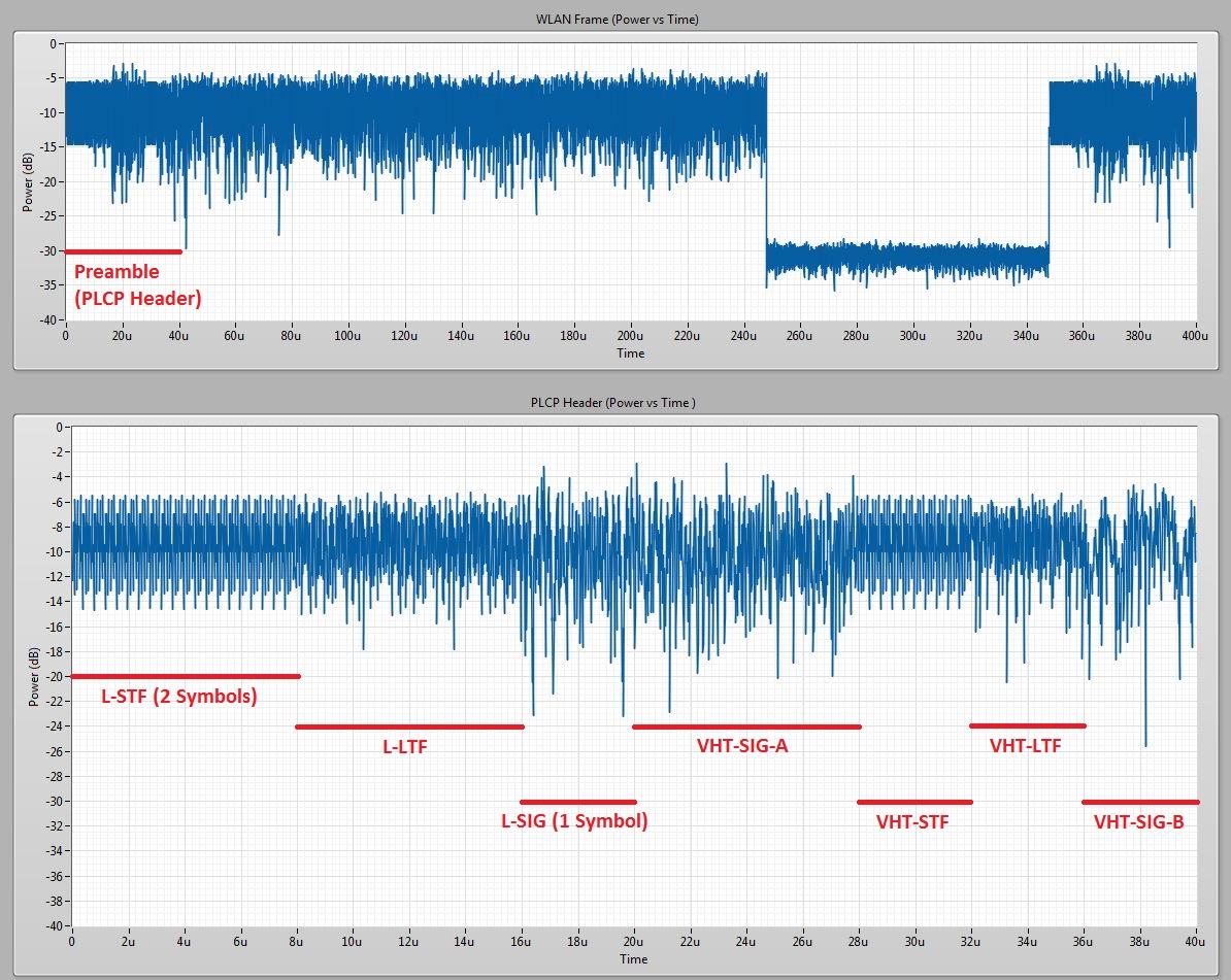
The example performs gated power measurements on the 802.11ac packet. Gated measurements allow the user to analyze a signal for a specific duration in time. A data packet is composed of a several fields of information in a sequence that makes up the Physical Layer Convergence Protocol (PLCP) header which is followed by the data payload. Together, PLCP header (pre-amble) and data payload make up one WLAN frame (PPDU). Refer to the diagram in Additional Images section to visualize the frame structure of the 802.11ac waveform. Using gated power measurements featured in the NI-WLAN Analysis Toolkit, the user can measure the power of each field of the PLCP header as well as the payload itself.
Description of each field in PLCP header:
|
Field Name |
Purpose |
OFDM Symbols |
Additional Notes |
|
L-STF |
Legacy field for backwards compatibility |
2 |
Repeated in each sub-band with phase rotation |
|
L-LTF |
Legacy field for backwards compatibility |
2 |
Repeated in each sub-band with phase rotation |
|
L-SIG |
Legacy field for backwards compatibility |
1 |
BPSK modulated |
|
VHT-SIG-A |
Contains information to interpret proceeding VHT packets, allowing auto-detection |
2 |
First symbol is BPSK modulated, second symbol is QBPSK |
|
VHT-STF |
Improves gain control estimation for MIMO |
1 |
|
|
VHT-LTF |
Provides means for the receiver to estimate the channel between each spatial mapping input (or spatial stream transmitter if no STBC is applied) and receive chain |
1 |
There can be a total of 1, 2, 4, 6, or 8 VHT-LTFs; each is 1 OFDM symbol |
|
VHT-SIG-B |
Specifies payload length and MCS for multi-user mode |
1 |
Bits are repeated in each sub-band |
Steps to Implement or Execute Code
- Open niWLAN 802.11ac Measure Power.vi
- Select the generation and analysis devices in the RFSG Resource and RFSA Resource controls, respectively.
- Run the VI.
Requirements
Software
LabVIEW 2013 Full Development System
NI-WLAN Toolkit 4.0.1
NI-RFSA 2.7.5
NI-RFSG 1.9.5
Hardware
NI-5644R or NI-5645R
Additional Information or References
http://www.radio-electronics.com/info/wireless/wi-fi/ieee-802-11ac-gigabit.php
Applications Engineer
National Instruments
http://www.ni.com/support
Example code from the Example Code Exchange in the NI Community is licensed with the MIT license.
- Mark as Read
- Mark as New
- Bookmark
- Permalink
- Report to a Moderator
apakah bisa menjalankan program ini tanpa perangkat keras tersebut
- Mark as Read
- Mark as New
- Bookmark
- Permalink
- Report to a Moderator
whether to run this program without the hardware
