Using the LabVIEW 2013 Supervisory Control and Data Acquisition (SCADA) System Sample Project
- Subscribe to RSS Feed
- Mark as New
- Mark as Read
- Bookmark
- Subscribe
- Printer Friendly Page
- Report to a Moderator
Code and Documents
Attachment
Description
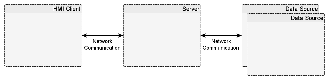
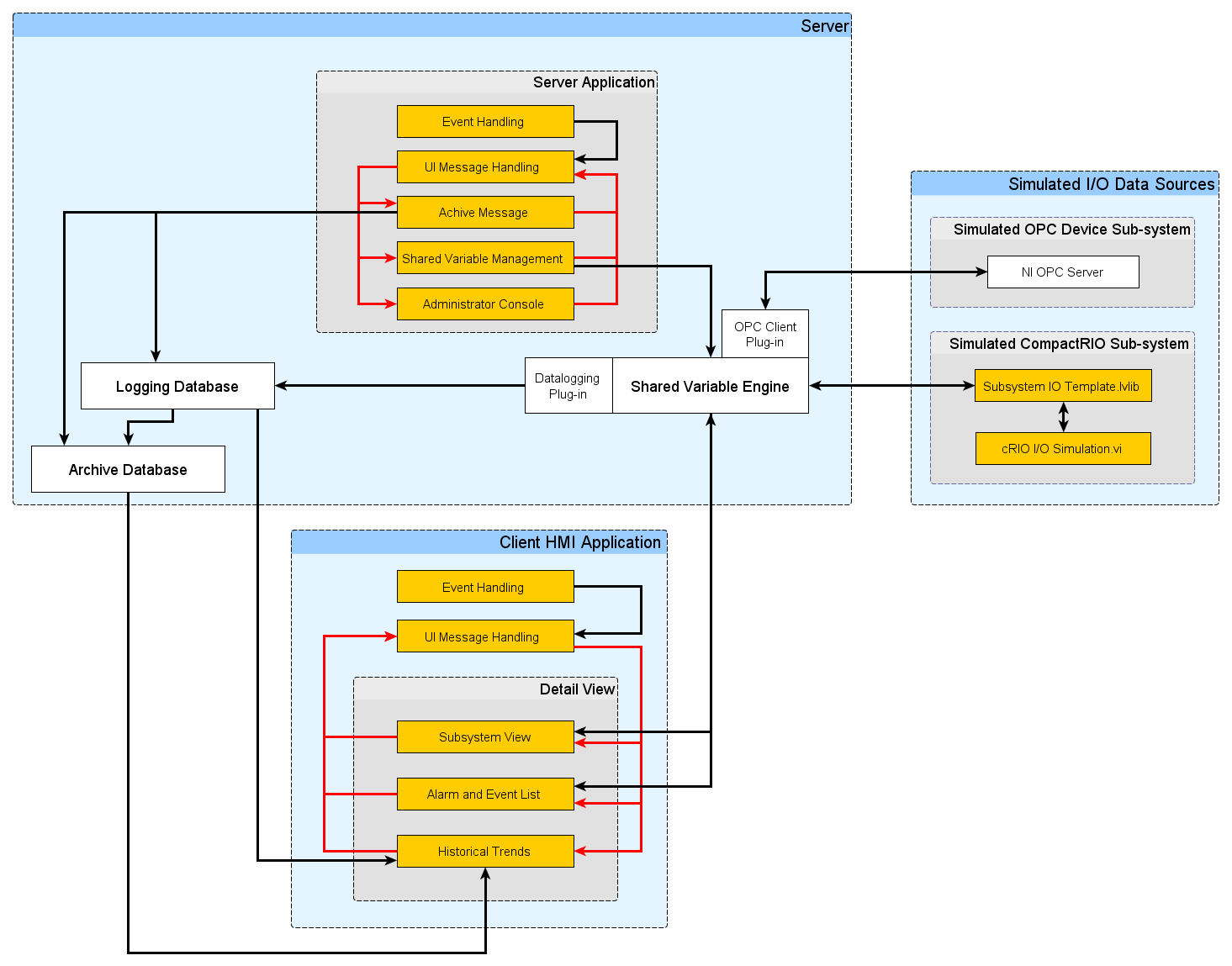
Description-Separate-1The attached document goes into detail on the architecture of the LabVIEW Supervisory Control and Data Acquisition System sample project available in LabVIEW 2013 DSC Module and later. You can see from the system diagram below that this sample project has VIs all running on a single system, but it simulates an entire SCADA system including: two data sources (PLC and CompactRIO), a server application, a client HMI application and historical data and alarm logging server. This document also provides best practices and coding techniques throughout.
To get a 20 minute tour of the SCADA System Sample Project, view the webcast.
Marketing Manager, NI Software
Example code from the Example Code Exchange in the NI Community is licensed with the MIT license.
- Mark as Read
- Mark as New
- Bookmark
- Permalink
- Report to a Moderator
Hi Jonah,
When I built an executable of this project, cRIO1.lvlib failed to deploy in run-time. PLC1.lvlib has no problem.
Do you have any idea why?
Thanks and regards
Khoa
Singapore (65) 6226 5886 | Malaysia (60) 3 7948 2000 | Thailand (66) 2 298 4800
Philippines (63) 2 659 1722 | Vietnam (84) 28 3911 3150 | Indonesia (62) 21 2783 2355
- Mark as Read
- Mark as New
- Bookmark
- Permalink
- Report to a Moderator
No I am not sure why it would not deploy. I just tried building the two exes into installers that are part of the sample project. I installed the installers (exes + DSC RTS) them on a clean machine and both the libraries seem to deploy and respond as expected.
To dig into the problem a bit more, how do you know the cRIO1.lvlib had a problem deploying? Did a section of code through an error? If so what was it? Please describe the situation a bit more.
Regards, jpaul
Marketing Manager, NI Software
- Mark as Read
- Mark as New
- Bookmark
- Permalink
- Report to a Moderator
I know it's an ancient thread, but I was wondering if anyone knows what the best way to add subsystems with different I/O attributes would be. At the moment, there's only one configuration file which defines the I/O for all subsystems, and the system I'm trying to build has distinctly different components (e.g. heating, turbine control, oil cooling subsystems) which need different inputs and outputs.
Thanks!
- Mark as Read
- Mark as New
- Bookmark
- Permalink
- Report to a Moderator
mmorawski, I am interested in the same, did you find a way how to do it?
This sample project is pretty useless, if there is no documentation on how to modify and add subsystems. It takes too much time to dig through all the VIs to find out how everything works.
It seems there hasn't been done much more work on the SCADA side by NI since this 2013 sample project? At least I can't find much on the web. There seem to be no discussions and no newer samples by NI, if I am seeing this right? The examples in the lvdsc-folder seem to be pretty old as well using different methods compared to this 2013 project.
- Mark as Read
- Mark as New
- Bookmark
- Permalink
- Report to a Moderator
No, I have not managed to find anything, AndreKunze, which is a shame because this project is exactly what I'm trying to build, but I will probably end up writing my own code, because it will be easier to do than to modify this one.
- Mark as Read
- Mark as New
- Bookmark
- Permalink
- Report to a Moderator
This reply is directed at AndreKunze and mmorawski's question. It is probably not useful to them anymore, but will hopefully give a lead to others pursuing the same setup in the future. I have not actually implemented this, so no guarantees that this will work, but here are my ideas after looking through the code for another reason.
I think it is possible to add a subsystem that is different than the currently defined subsystem without changing all of the subsystem variables by adding/changing a few items:
- Create a new Subsystem IO Attributes.csv file that is specific to this new type of subsystem we want to define. We will create a new attributes csv file for each unique subsystem that we need.
- Alter the Global - Server.vi to add in each new unique Subsystem IO Attributes csv that you create. (Eg if you add in two additional unique subsystems, in the server global, you should now have the original "Subsystem I/O Attributes File" as well as two other items maybe named "Subsystem I/O Attributes File 1" and "Subsystem I/O Attributes File 2" (or a better more identifiable name).)
- Alter the Global - Server.vi to add in a new "Subsystem I/O Attributes" for each new unique subsystem you create. This is similar to the previous step. Since these are .ctl's it means that for each new "Subsystem I/O Attirbutes" you create, you will also have to make a .ctl file for it. So, the step should probably be the make the unique .ctl first, then add it into the server global.
- In Server Main.vi you will need to add "Get Configuration File Path.vi"s equal to the number of csv files you created. This is at the very beginning of the VI where the config files have their info populated into the server globals.
- In Read Server Configuration.vi you will need to add duplicates of what is currently there for "Subsystem I/O Attributes File" and "Subsystem I/O Attributes". I believe this VI reads from the csv file and loads the info into the server global. So, we will want to make sure we are loading all of our unique subsystems here. If we stick to the format of the existing csv file, I don't think changes will need to be mad to the Load Subsystem IO Attributes VI .
- A similar update will need to be done to Get Server Configuration.vi and Save Server Configuration.vi .
- You will also want to update View Subsystem I/O Attributes Dialog.vi so that the dialog is updated properly when you look at the server variables.
- One last place that I believe you will need to make changes is in the Server Main.vi >> UI Message Loop >> "Exit" case. This is where Data Value References (DVRs) are deleted. Since we created more "Subsystem I/O Attributes" we will want to make sure we are deleting them here as well.
The likely-hood of me overlooking something is very high, but this is where I would start if I was adding >=1 new unique subsystems to this project. Please make corrections to the above steps or add to it as you see fit.
- Mark as Read
- Mark as New
- Bookmark
- Permalink
- Report to a Moderator
While working with this example project, I found that when variables went into an alarm state their values would no longer update on the Client Main front panel. After digging in a bit more, I found it was because of the Quality value that was returned in the <shared variable value change notification> User Event in the Event Handling Loop. In the default Client Main VI only Quality values of 0 enqueue a "Value Change Notification" message. However, this is not always desirable, because maybe we want our front panel to continue updating even when we are in an alarm state.
So, what does the Quality value mean? Quality makes sense when it is interpreted on a bit level. There are 36 bits that make up the Quality value. The meaning of each of these bits are specified in the Datasocket Read Function help (https://www.ni.com/docs/en-US/bundle/labview-api-ref/page/functions/datasocket-read.html). For example, if our variable is in an alarm state, then bit 30 will contain a value of 1. If there are no other bits activated, then we will read back a Quality value of 536870912 if read in base 10, decimal, or 100000000000000000000000000000 if converted to binary representation.
How do I filter if I want different active bit values to go into different case structures in Client Main.vi :: Event Handling Loop :: <shared variable value change notification>:User Event?
By default there are only two cases, 0 and default. To filter by different bit numbers, you can either make cases for every number that can be represented by 30 bits, or make groupings of such cases, or you can use bitwise logic (logical AND) to mask out bits you don't care about and only look at the bits that are important to you.
