by:
03-10-2015
06:14 AM
Last Edited by:
 Content Cleaner
06-16-2025
02:46 PM
Content Cleaner
06-16-2025
02:46 PM
Products and Environment
This section reflects the products and operating system used to create the example.
To download NI software, including the products shown below, visit ni.com/downloads.
Hardware
- VirtualBench All-in-One Instrument
Code and Documents
Attachment
Description
Description-Separate-1Overview
This example automates the digital input output (DIO) channels to master I2C commands and performs a read.
[+] Enlarge Image
Steps to Run Program
-
- Download the example program on the right under downloads.
- In LabVIEW software, open the program by going to File » Open… and navigating to the file.
- Connect the VirtualBench device.
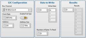
- Select the correct VirtualBench bus channel from the pull-down menu of the VirtualBench Bus Channel control. Set the clock rate, address, and address size as desired; specify whether to enable pull-up resistors. Specify the data to write and number of bytes to read.
- Click the Run button to write and read data.
- The data acquired will display in the Results indicator.
Program Explained
[+] Enlarge Image
-
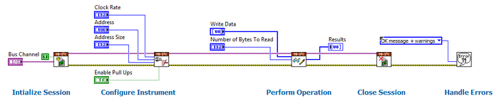
- Initialize Session
- The VirtualBench bus channel is passed into the I2C Initialize VI to initialize a new session on the I2C engine for the device.
- A Boolean true constant is also passed into the VI to reset the device to default values.
- Configure Instrument
- Instrument and error information are passed into the I2C Configure Bus VI along with the clock rate, address, and address size.
- The Boolean control will pass a true or false value to the VI depending on the front panel settings in order to specify if pull-up resistors should be enabled.
- Perform Operation
- Instrument and error information are passed to the I2C Write Read VI.
- The data to write and the number of bytes to read are passed into the VI, and then the VI performs a write followed by a read.
- The VI outputs the data read to the indicator on the front panel.
- Close Session
- The instrument and error information are passed to the I2C Close VI. This closes the session and deallocates any resources for the next time a session is created with the instrument.
- Handle Errors
- Finally, the error information is passed into the Simple Error Handler VI. If an error has occurred, a dialog box will open to notify the user.
Additional Resources
VirtualBench Examples
-
- Single Instruments
- Multiple Instruments
Description-Separate-2
Example code from the Example Code Exchange in the NI Community is licensed with the MIT license.
