- Subscribe to RSS Feed
- Mark Topic as New
- Mark Topic as Read
- Float this Topic for Current User
- Bookmark
- Subscribe
- Mute
- Printer Friendly Page
H-Bridge Dual Motor Driver Project for sbRIO-96XX
10-30-2016
03:52 PM
- last edited on
03-06-2024
02:56 PM
by
![]() migration-bot
migration-bot
- Mark as New
- Bookmark
- Subscribe
- Mute
- Subscribe to RSS Feed
- Permalink
- Report to a Moderator
Overview:
The H-Bridge is a common topology used to drive and control brushed DC motors. It enables the voltage to be applied across the motor in either direction, therefore allowing the motor to run forward, backward as well as providing break (sudden stop), free run, speed and torque control.
sbRIO-96XX as Intelligent Motor Controller:
Figure 1 is the block diagram of the sbRIO platform developing system configured as a controlling mechanism for DC dual H-Bridge motor driver system. We are using NI sbRIO-9626 and our custom designed breakout and daughter boards (called personality module) as well as an off the shelf Dual H-Bridge MOSFET driver module which was purchased on Amazon for under $30. The personality module shown in the block diagram consist of an isolated DC-DC converter and opto coupling circuits for interfacing to the digital I/O lines of the sbRIO device. Included are also, a 24V/15A DC power supply and a custom-made rotary encoder wheel and circuit for monitoring and controlling the speed of brushed DC motors.

Figure 1: Block Dig of the sbRIO-96XX Dual H-Bridge Motor Driver
Figure 2, shows the assembled personality module with the Dual DC motor driver circuit board installed. This module mates with the sbRIO breakout board and will have access to all FPGA data lines. Figure 3, shows the Dual Motor Drive system consisting of sbRIO development system, two 250W brushed DC motors, rotary encoder wheel, 24V/15A power supply and the second sbRIO breakout board with the personality module installed. The second breakout board is mounted externally and is connected to the sbRIO development system via shielded cable. It is possible to connect multiple breakout boards to a single sbRIO device.

Figure 2: Personality Module and Dual DC Motor Driver H-Bridge Circuit Board

Figure 3: Hardware setup for Dual DC Motor Driver System
Hardware Setup:
Three digital lines are used for controlling and monitoring speed of each motor as follow,
DIO0: Motor 1 direction, High= Forward, Low= Reverse
DIO1: Motor 1 speed control (PWM)
DIO2: Motor 1 speed monitor (counts motor’s revolution / min)
DIO3: Motor 2 direction, High=Forward, Low= Reverse
DIO4: Motor 2 speed control (PWM)
DIO5: Motor 2 speed monitor (counts motor’s revolution / min)
The Dual H-Bridge Motor driver board has the following specification,
Rated current of 10A per channel
Peak current of 30A per channel
Break function
0 – 99% PWM duty cycle
Motors:
AmpFlow Brushed DC motors, 250W, 12V,24, 36V, 3400rpm
Other possible scenarios:
In this scenario, we are using a DC motor control power shield kit from Infineon Technologies connected to the same personality module mentioned above (Figure 4). This kit is capable of driving two uni-directional DC motors in half bridge configuration or one bi-directional in H-bridge configuration. It can be easily interface to the sbRIO digital lines and controlled via the PWM generated by the FPGA.
Kit’s Features:
Capable of high frequency PWM up to 30KHz
Diagnosis with current sense
Protection against over current and temperature
Brushed DC motor control up to 250W
Nominal input voltage of 8-18V up to 40V max
Average motor current of 30A
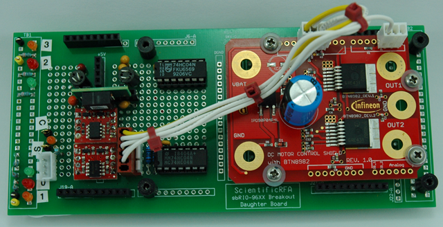
Figure 4: Personality Module with Infineon Dual DC Motor Driver
High Speed High Power Configurable H-Bridge:
Figure 5, is the block diagram of 2-channels of high power and high speed switching system currently under development that mate directly with the sbRIO’s breakout board. Each channel can independently control and monitor voltages up to 600V and current up to 20Amp AC or DC. The two channels can be configured as half-bridge or two boards can be stacked together to form an H-bridge circuit. Channels are designed with extensive circuit protections, e.g. isolated DC-DC power supply as well as opto coupling interface to sbRIO’s digital and analog lines. The output power transistors are either MOSFETs or IGBT depending on the application.
Highlighted Features:
Direct interface to the sbRIO-96XX platform via sbRIO’s Breakout board
High voltage handling capability, up to 600V AC or DC
High current handling capability, up to 20Amp per channel
Switching frequency up to 80KHz
Configurable as a single switch, half-bridge or H-Bridge (when stacked with second similar board)
Built-in extensive circuit protection
Applications:
Industrial, Battery Powered Cars, Robotic, Scientific, High power magnetic design/testing and more.

Figure 5: Block diagram of High Power High Speed 2 Ch Switching Sys
Project Hardware and Software Setup:
Figure 6 is the snapshot of the Project Explorer for the “sbRIO Dual Motor Driver H-Bridge” project, which contains sbRIO-9626 with two C-modules installed and connected through the local area network. Figure 7, is the Main (FPGA) VI that connects to the local host server and communicates with the host software after it is compiled. Figure 8, is the main Host.vi that runs on the host computer for controlling and adjusting speed of each motor independently. Figure 9 and 10 are snapshots of the FPGA generated variable frequency and the PWM for each motor.

Figure 6: sbRIO Dual Motor Driver H-Bridge Project

Figure 7: sbRIO Dual Motor Driver FPGA Main.vi

Figure 8: Dual DC Motor Driver 3rd Party HW Host.vi

Figure 9: Motor Speed Control at 10KHz with 2% Duty Cycle

Figure 10: Motor Speed Control at 10KHz with 95% Duty Cycle
sbRIO-96XX Dual DC Motor Driver with the 3rd Party Hardware
Download the "sbRIO Dual Motor Driver H-Bridge" project, follow the instructions on the host VI for operation.
Requirement: LabVIEW 2013 or above.
Related Links:
- sbRIO-96XX series DIO/MIO Breakout and Development Board
- Precision Programmable Power Supply
- Slide show demonstrating this development system
- How to Develop and Create Virtually Unlimited Number of Diverse Products by Using a Single Hardware ...
