- Subscribe to RSS Feed
- Mark Topic as New
- Mark Topic as Read
- Float this Topic for Current User
- Bookmark
- Subscribe
- Mute
- Printer Friendly Page
Labview i/f for Arduino: Correctly producing PWM output
01-11-2012 04:19 PM
- Mark as New
- Bookmark
- Subscribe
- Mute
- Subscribe to RSS Feed
- Permalink
- Report to a Moderator
I'm getting:
Warning 1073676294 occurred at VISA Read in LabVIEW Interface for Arduino.lvlib:Send Receive.vi->LabVIEW Interface for Arduino.lvlib:PWM Write Pin.vi->Arduino PWM Trial.vi
Possible reason(s):
VISA: (Hex 0x3FFF0006) The number of bytes transferred is equal to the requested input count. More data might be available.
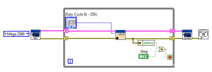
Just for the feedback, I'm controlling a computer fan (thru transistor) with the PWM. I'm just trying to get everything talking together. The fan is running as I intended it to, but now I just want to know how to stop getting this warning. I've tinkered around but for the sake of this question, I simplified to the version you see above.
Thanks!
01-11-2012 04:32 PM
- Mark as New
- Bookmark
- Subscribe
- Mute
- Subscribe to RSS Feed
- Permalink
- Report to a Moderator
Hello,
To prevent this error, you need to configure your the PWM pin as an output. The PWM Write default pin is pin 3, and you can use the Set Digital Pin Mode VI to set it as an output. You can also see this KnowledgeBase for more information on this error,
Julianne
Systems Engineer, Embedded Systems
Certified LabVIEW Architect, Certified LabVIEW Embedded Systems Developer
National Instruments
01-12-2012 04:07 PM
- Mark as New
- Bookmark
- Subscribe
- Mute
- Subscribe to RSS Feed
- Permalink
- Report to a Moderator
Alright, I added the set digital pin mode immediately after the init (and outside the while loop). I'm feeding it "3" to the Digital I/O Pin input, plus a constant Output to the "Pin Mode (Input)" input.
I get the same warning.
So then I tried PWM Configure Port, and I now get error 5001, which totally aborts my program. I also don't know what is the use of the output array, "PWM Pins." The lack of documentation for these vi's within Labview is frustrating.
01-12-2012 07:09 PM
- Mark as New
- Bookmark
- Subscribe
- Mute
- Subscribe to RSS Feed
- Permalink
- Report to a Moderator
Hi,
The output array, PWM Pins, is used in the PWM Configure Port and the PWM Write Port. Please ensure that you are using the PWM Write Pin instead of the Write Port Version. The PWM Configure Port just sets multiple pins to outputs, so it does the same thing as the Set Digital Pin Mode.
Error 5001 means that the pin does not exist or is in use. The PWM Configure Port function accesses multiple pins (3,5 and 6 by default) - were you using these pins for anything else? Try using the PWM Write Pin function.
Also, does the warning occur only in the larger program as well as the simplified version above?
- Julianne
Systems Engineer, Embedded Systems
Certified LabVIEW Architect, Certified LabVIEW Embedded Systems Developer
National Instruments
