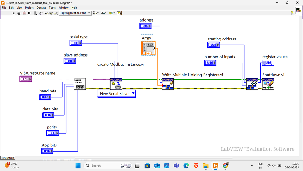
the test i'm doing is between STM32 board as master and LabVIEW as slave using modbus API library.
where STM32(master) request to read data from LabVIEW.
the hardware im using is "STM32 board", "RS485 to TTL converter", "USB RS485 converter"
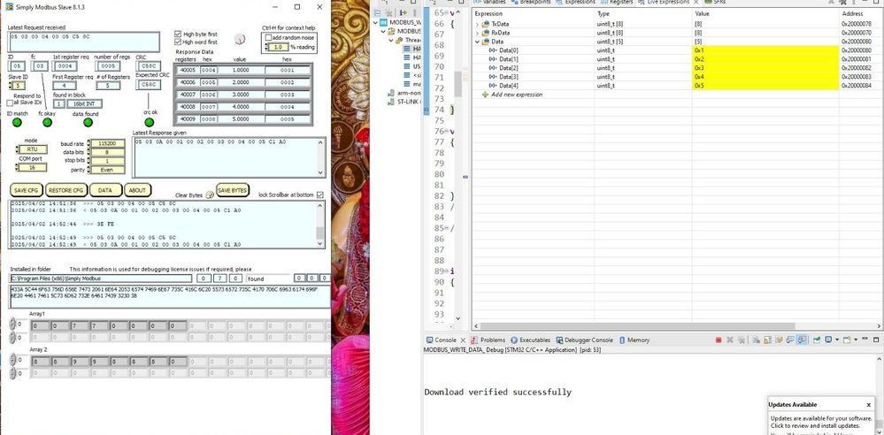
i have worked with "SIMPLY MODBUS SLAVE" software as slave and "stm32" as master and i have attached the screenshot with it where you can see the the data in debug mode of stmcube ide given by the "simple modbus slave"
i have given below stm32 code
/* USER CODE BEGIN Header */
/**
******************************************************************************
* @file : main.c
* @brief : Main program body
******************************************************************************
* @attention
*
* Copyright (c) 2025 STMicroelectronics.
* All rights reserved.
*
* This software is licensed under terms that can be found in the LICENSE file
* in the root directory of this software component.
* If no LICENSE file comes with this software, it is provided AS-IS.
*
******************************************************************************
*/
/* USER CODE END Header */
/* Includes ------------------------------------------------------------------*/
#include "main.h"
#include "modbus_crc.h"
/* Private includes ----------------------------------------------------------*/
/* USER CODE BEGIN Includes */
/* USER CODE END Includes */
/* Private typedef -----------------------------------------------------------*/
/* USER CODE BEGIN PTD */
/* USER CODE END PTD */
/* Private define ------------------------------------------------------------*/
/* USER CODE BEGIN PD */
/* USER CODE END PD */
/* Private macro -------------------------------------------------------------*/
/* USER CODE BEGIN PM */
/* USER CODE END PM */
/* Private variables ---------------------------------------------------------*/
UART_HandleTypeDef huart2;
/* USER CODE BEGIN PV */
/* USER CODE END PV */
/* Private function prototypes -----------------------------------------------*/
void SystemClock_Config(void);
static void MX_GPIO_Init(void);
static void MX_USART2_UART_Init(void);
/* USER CODE BEGIN PFP */
/* USER CODE END PFP */
/* Private user code ---------------------------------------------------------*/
/* USER CODE BEGIN 0 */
uint8_t RxData[8];
uint8_t TxData[8];
int Data[16];
int indx = 0;
void HAL_UARTEx_RxEventCallback(UART_HandleTypeDef *huart, uint16_t Size)
{
}
void sendData (uint8_t *data)
{
HAL_GPIO_WritePin(TX_EN_GPIO_Port, TX_EN_Pin, GPIO_PIN_SET);
//HAL_Delay(100);
HAL_UART_Transmit(&huart2, data,8, 1000);
HAL_GPIO_WritePin(TX_EN_GPIO_Port,TX_EN_Pin , GPIO_PIN_RESET);
}
/* USER CODE END 0 */
/**
* @brief The application entry point.
* @retval int
*/
int main(void)
{
/* USER CODE BEGIN 1 */
/* USER CODE END 1 */
/* MCU Configuration--------------------------------------------------------*/
/* Reset of all peripherals, Initializes the Flash interface and the Systick. */
HAL_Init();
/* USER CODE BEGIN Init */
/* USER CODE END Init */
/* Configure the system clock */
SystemClock_Config();
/* USER CODE BEGIN SysInit */
/* USER CODE END SysInit */
/* Initialize all configured peripherals */
MX_GPIO_Init();
MX_USART2_UART_Init();
/* USER CODE BEGIN 2 */
HAL_UARTEx_ReceiveToIdle_IT(&huart2, RxData, 32);
TxData[0] = 0x05; // slave address
TxData[1] = 0x03; // Force single coil
TxData[2] = 0; // coil address high
TxData[3] = 0X04; // coil address low
//The coil address will be 00000000 00000000 = 0 + 1 = 1
TxData[4] = 0; // force data high
TxData[5] = 0X05; // force data low
// uint8_t TxData[8] = {0x05, 0x05, 0x00, 0x00, 0xFF, 0x00, 0x00, 0x00}; // 8-byte buffer
/*
TxData[1] = 0x06; // Preset single Register
TxData[2] = 0; // Register address high
TxData[3] = 5; // Register address low
//The coil address will be 00000000 00000101 = 5 + 40001 = 40006
TxData[4] = 0x12; // Preset data high
TxData[5] = 0x34; // Preset data low
*/
/*
TxData[1] = 0x0F; // Force Multiple coils
TxData[2] = 0; // coil address high
TxData[3] = 0; // coil address low
//The coil address will be 00000000 00000000 = 0 + 1 = 1
TxData[4] = 0; // no. of coils high
TxData[5] = 0x0F; // no. of coils low
// Total no. of coils = 00000000 00001111 = 15 coils
TxData[6] = 2; // Byte count (15 coils would need 2 bytes)
TxData[7] = 0x35; // Data for first 8 coils
TxData[8] = 0x74; // Data for next 8 coils (actually 7 coils)
*/
/* TxData[1] = 0x10; // Preset Multiple Registers
TxData[2] = 0; // Register address high
TxData[3] = 0; // Register address low
//The coil address will be 00000000 00000000 = 0 + 40001 = 40001
TxData[4] = 0; // no. of Registers high
TxData[5] = 0x03; // no. of Registers low
// Total no. of Registers = 00000000 00000011 = 3 Registers
TxData[6] = 6; // Byte count (3 Registers would need 6 bytes (2 bytes per register))
TxData[7] = 0x12; // Data High for first Register
TxData[8] = 0x34; // Data low for first Register
TxData[9] = 0x56; // Data High for 2nd Register
TxData[10] = 0x78; // Data low for 2nd Register
TxData[11] = 0xab; // Data High for 3rd Register
TxData[12] = 0xcd; // Data low for 3rd Register */
uint16_t crc = crc16(TxData, 6);
TxData[6] = crc&0xFF; // CRC LOW
TxData[7] = (crc>>8)&0xFF; // CRC HIGH
sendData(TxData);
/* USER CODE END 2 */
/* Infinite loop */
/* USER CODE BEGIN WHILE */
while (1)
{
/* USER CODE END WHILE */
/* USER CODE BEGIN 3 */
}
/* USER CODE END 3 */
}
/**
* @brief System Clock Configuration
* @retval None
*/
void SystemClock_Config(void)
{
RCC_OscInitTypeDef RCC_OscInitStruct = {0};
RCC_ClkInitTypeDef RCC_ClkInitStruct = {0};
/** Configure the main internal regulator output voltage
*/
__HAL_RCC_PWR_CLK_ENABLE();
__HAL_PWR_VOLTAGESCALING_CONFIG(PWR_REGULATOR_VOLTAGE_SCALE1);
/** Initializes the RCC Oscillators according to the specified parameters
* in the RCC_OscInitTypeDef structure.
*/
RCC_OscInitStruct.OscillatorType = RCC_OSCILLATORTYPE_HSE;
RCC_OscInitStruct.HSEState = RCC_HSE_ON;
RCC_OscInitStruct.PLL.PLLState = RCC_PLL_ON;
RCC_OscInitStruct.PLL.PLLSource = RCC_PLLSOURCE_HSE;
RCC_OscInitStruct.PLL.PLLM = 8;
RCC_OscInitStruct.PLL.PLLN = 336;
RCC_OscInitStruct.PLL.PLLP = RCC_PLLP_DIV2;
RCC_OscInitStruct.PLL.PLLQ = 7;
if (HAL_RCC_OscConfig(&RCC_OscInitStruct) != HAL_OK)
{
Error_Handler();
}
/** Initializes the CPU, AHB and APB buses clocks
*/
RCC_ClkInitStruct.ClockType = RCC_CLOCKTYPE_HCLK|RCC_CLOCKTYPE_SYSCLK
|RCC_CLOCKTYPE_PCLK1|RCC_CLOCKTYPE_PCLK2;
RCC_ClkInitStruct.SYSCLKSource = RCC_SYSCLKSOURCE_PLLCLK;
RCC_ClkInitStruct.AHBCLKDivider = RCC_SYSCLK_DIV1;
RCC_ClkInitStruct.APB1CLKDivider = RCC_HCLK_DIV4;
RCC_ClkInitStruct.APB2CLKDivider = RCC_HCLK_DIV2;
if (HAL_RCC_ClockConfig(&RCC_ClkInitStruct, FLASH_LATENCY_5) != HAL_OK)
{
Error_Handler();
}
}
/**
* @brief USART2 Initialization Function
* @param None
* @retval None
*/
static void MX_USART2_UART_Init(void)
{
/* USER CODE BEGIN USART2_Init 0 */
/* USER CODE END USART2_Init 0 */
/* USER CODE BEGIN USART2_Init 1 */
/* USER CODE END USART2_Init 1 */
huart2.Instance = USART2;
huart2.Init.BaudRate = 115200;
huart2.Init.WordLength = UART_WORDLENGTH_9B;
huart2.Init.StopBits = UART_STOPBITS_1;
huart2.Init.Parity = UART_PARITY_EVEN;
huart2.Init.Mode = UART_MODE_TX_RX;
huart2.Init.HwFlowCtl = UART_HWCONTROL_NONE;
huart2.Init.OverSampling = UART_OVERSAMPLING_16;
if (HAL_UART_Init(&huart2) != HAL_OK)
{
Error_Handler();
}
/* USER CODE BEGIN USART2_Init 2 */
/* USER CODE END USART2_Init 2 */
}
/**
* @brief GPIO Initialization Function
* @param None
* @retval None
*/
static void MX_GPIO_Init(void)
{
GPIO_InitTypeDef GPIO_InitStruct = {0};
/* USER CODE BEGIN MX_GPIO_Init_1 */
/* USER CODE END MX_GPIO_Init_1 */
/* GPIO Ports Clock Enable */
__HAL_RCC_GPIOC_CLK_ENABLE();
__HAL_RCC_GPIOH_CLK_ENABLE();
__HAL_RCC_GPIOA_CLK_ENABLE();
/*Configure GPIO pin Output Level */
HAL_GPIO_WritePin(TX_EN_GPIO_Port, TX_EN_Pin, GPIO_PIN_RESET);
/*Configure GPIO pin : TX_EN_Pin */
GPIO_InitStruct.Pin = TX_EN_Pin;
GPIO_InitStruct.Mode = GPIO_MODE_OUTPUT_PP;
GPIO_InitStruct.Pull = GPIO_NOPULL;
GPIO_InitStruct.Speed = GPIO_SPEED_FREQ_LOW;
HAL_GPIO_Init(TX_EN_GPIO_Port, &GPIO_InitStruct);
/* USER CODE BEGIN MX_GPIO_Init_2 */
/* USER CODE END MX_GPIO_Init_2 */
}
/* USER CODE BEGIN 4 */
/* USER CODE END 4 */
/**
* @brief This function is executed in case of error occurrence.
* @retval None
*/
void Error_Handler(void)
{
/* USER CODE BEGIN Error_Handler_Debug */
/* User can add his own implementation to report the HAL error return state */
__disable_irq();
while (1)
{
}
/* USER CODE END Error_Handler_Debug */
}
#ifdef USE_FULL_ASSERT
/**
* @brief Reports the name of the source file and the source line number
* where the assert_param error has occurred.
* @param file: pointer to the source file name
* @param line: assert_param error line source number
* @retval None
*/
void assert_failed(uint8_t *file, uint32_t line)
{
/* USER CODE BEGIN 6 */
/* User can add his own implementation to report the file name and line number,
ex: printf("Wrong parameters value: file %s on line %d\r\n", file, line) */
/* USER CODE END 6 */
}
#endif /* USE_FULL_ASSERT */
this is the format to read data from LabVIEW:-
[11:34 am, 26/3/2025] Anurag Thorat: read data from slave code
[11:35 am, 26/3/2025] Anurag Thorat: 0x05; slave address
[11:35 am, 26/3/2025] Anurag Thorat: 0x03; command forb read data from register
[11:43 am, 26/3/2025] Anurag Thorat: message format for read data from slave
TxData[0] = 0x05; // slave address
TxData[1] = 0x03; // Function code for Read Holding Registers
TxData[2] = 0; // register address high
TxData[3] = 0X04; // register address low
TxData[2] = 0;
TxData[3] = 0x04;
//The Register address will be 00000000 00000100 = 4 + 40001 = 40005
TxData[4] = 0;
TxData[5] = 0x05;
// no of registers to read will be 00000000 00000101 = 5 Registers = 10 Bytes
uint16_t crc = crc16(TxData, 6);
TxData[6] = crc&0xFF; // CRC LOW
TxData[7] = (crc>>8)&0xFF; // CRC HIGH
this is the LabVIEW block diagram screenshot and front panel screenshot, so please help me its not showing any error at labview side but stm32 doest show any data when we check in debug mode......


