LabVIEW

cancel
Showing results for 
Search instead for 
Did you mean: 

Write Continous Analog Output using DAQmx to Control Valves

I am trying to control 13 solenoid valves sequentially.  The VI I have attached uses a case structure system with shift registers that will perform several tasks. Such as open and close the valves, read in temperature, %CO2 Concentration, and flow rate, close the valve, and then write the data to a file.  The command that actually opens and closes the valves is outside of the case structures.  The case structure sends out an array of T/F constants which correspond to each valve, and this array is unbundled by name outside of the case structure. So, each valve can be turned on and off individually.  My question is, how do you write a constant output to each of the valves that does not change until the T/F value of the valve in the array in the case structure changes?  I've looked at the NI tutorial video on using DAQmx to send out a finite analog output, and have gotten the example to work.  They mention that you can achieve continous analog output.  However, the do not show how to achieve it.

ps.  The VI as it currently is, is trying to send a control signal of +5V to analog output 0.

Thanks
0 Kudos
Message 1 of 14
(3,724 Views)

I'm a little confused about your question but a lot confused about your program. You have said earlier that you were going to be using a 9472 so you should be using digital I/O. Even if you were using analog, then you've made things several times come complex than it needs to be. No reason at all for the basic function generator and all of that DAQmx timing. Just use Analog>Single Channel>Single Sample and wire a scalar to it. You can also set multiple channels.

For writing to digital, select Digital>Multiple Channels>Single Sample>1D Boolean. With the cluster, wire up a Cluster to Array function and wire the output of that to the DAQmx Write.

With each iteration of the loop, you would be doing a DAQmx Write but if the data is the same as the last iteration, that's not a problem at all. You should have the DAQmx Create Channel, DAQmx Start Task and DAQmx Stop Task outside the loop.

0 Kudos
Message 2 of 14
(3,710 Views)
I do not have the 9472 on hand right now. So, I am designing test programs on DAQ board we already have while we are waiting for the 9472 to arrive. I'm sorry for making it complicated. I am relatively new to LabVIEW. So, I don't know what some of the functions are or how to  use them.


0 Kudos
Message 3 of 14
(3,701 Views)
Then design your program to use the digital I/O of the card that you do have. I don't know if you got the link in some of your other posts so if you did already, again its http://zone.ni.com/devzone/cda/tut/p/id/5434.
0 Kudos
Message 4 of 14
(3,690 Views)
Thanks for the help.  I VI attached has only one analog output, and I am trying to write the valve information to the 8 bit Digital I/O port on my block terminal.  I can run the VI just with the analog output sending out 5 volts whenever valve 1 is selected. However, whenever I try to add the digital port I receive Error-200524 saying the number of channels doesn't equal the number of tasks.  It says there are 13 channels, for the 13 valves, but only one task.  I know I have 13 outputs but only 8 bits on the Digital I/O port. Would that have something to do with the error?  I was able to control an individual bit, and I have attached that VI too.
0 Kudos
Message 5 of 14
(3,670 Views)
Well, when you have the real hardware, you'll have 13 digital I/O lines but in the meantime, do an array subset (get the first 8 elements) of the Boolean array and wire that to the digital DAQmw Write.
 
You really don't need the analog write at all. If you do want to write a single value to an analog output, you have the wrong type of DAQmx Write. It should be Analof DBL 1Chan 1Samp and not Analog Wfm 1Chan 1Samp. When you have it correct, you just wire a scalar to the data input.
 
p.s. Your whole logic with the cluster array is also needlessly complex. You don't need to delete a row at all. With an array, you probably just need to wire the iteration terminal to the index array function. You can also get rid of the array altogether. It looks like you are simply walking a single true through the array. That's a numeric that you can calculate from the iteration terminal and numerics can be wired to a digital DAQmx Write. First loop is 1, then 2, then 4, then 8, then 16. See the pattern? You can use the Power of 2 function.


Message Edited by Dennis Knutson on 07-25-2008 10:43 AM
0 Kudos
Message 6 of 14
(3,665 Views)
I have added the Array Subset and have it set to get the first 8 elements.  However, I am still receiving that same error, 8 Channels, 1 Task.  Does this error have something to do with multithreading the outputs on the PCI-6024E?  I looked at the link you gave me a couple post ago, and I thought it said the 6024E supported multithreading.
0 Kudos
Message 7 of 14
(3,659 Views)
Sorry, I forgot that the DAQmx Create Channel default is One Channel for All Lines. On the Line Grouging Input of the DAQmx Create Channel, right click and select 'Create Constat'. Change the constant to One Channel for Each Line.
0 Kudos
Message 8 of 14
(3,646 Views)

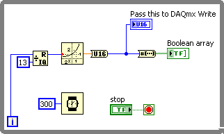
And this is what I was talking about to generate the basic pattern. Get rid of the Boolean cluster and the array you made from it. The DAQmx Write can be changed from 1D Bool to 1D U16.


Message Edited by Dennis Knutson on 07-25-2008 12:03 PM
0 Kudos
Message 9 of 14
(3,640 Views)
Thanks, I've gotten the Digital I/O to cycle.  Is the basic pattern loop you created to replace the 13X13 array-cluster?
0 Kudos
Message 10 of 14
(3,630 Views)