- Subscribe to RSS Feed
- Mark Topic as New
- Mark Topic as Read
- Float this Topic for Current User
- Bookmark
- Subscribe
- Mute
- Printer Friendly Page
switch
02-23-2007 09:08 AM
- Mark as New
- Bookmark
- Subscribe
- Mute
- Subscribe to RSS Feed
- Permalink
- Report to a Moderator
02-23-2007 09:26 AM - edited 02-23-2007 09:26 AM
- Mark as New
- Bookmark
- Subscribe
- Mute
- Subscribe to RSS Feed
- Permalink
- Report to a Moderator
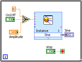
Are you talking about the Simulate Signal Express VI? If you are, I don't know what you mean by 'single phase power supply'. The Express VI has a phase input but that is not related to any power supply.
If you are using the Express VI and want to simulate turning the signal on and off, just do something like the code below.
Message Edited by Dennis Knutson on 02-23-2007 08:26 AM
02-23-2007 10:22 AM
- Mark as New
- Bookmark
- Subscribe
- Mute
- Subscribe to RSS Feed
- Permalink
- Report to a Moderator
hi Dennis,
thanks for your assitance. i will try and see how it works on the simulation.
However i need to incorporate an LED at the sine output (GRAPHICAL DISPLAY) to indicate that the signal in ON (GENERATED).
Thanks veteran.
Wale
02-23-2007 10:40 AM - edited 02-23-2007 10:40 AM
- Mark as New
- Bookmark
- Subscribe
- Mute
- Subscribe to RSS Feed
- Permalink
- Report to a Moderator
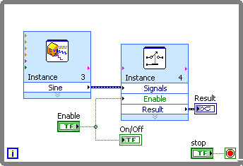
If you want an additional indication of the signal besides the On/Off button, just wire an indicator up to the control.
I guess I don't really understand what the real issue is. You can't connect or disconnect a wire on the diagram. If you have a graph as an indicator, data always has to wired to it. The data can be an array that simulates a sine wave, an array of zeroes as in my example, an array of NaN, in which the graph will be blank, or an empty array, in which case the graph will not update. The latter can be done with the Relay Express VI.
Message Edited by Dennis Knutson on 02-23-2007 09:40 AM
02-26-2007 06:18 AM
- Mark as New
- Bookmark
- Subscribe
- Mute
- Subscribe to RSS Feed
- Permalink
- Report to a Moderator
hi,
Assuming i have three different input (numreic controls) to be controlled by a three way switch, with one input (numric control) to be my source at any particular time, how do i go about constructing the three way switch.
Thanks for the last insight.
Wale
02-26-2007 06:29 AM
- Mark as New
- Bookmark
- Subscribe
- Mute
- Subscribe to RSS Feed
- Permalink
- Report to a Moderator
hi,
Assuming i have three different input (numeric controls) to be controlled by a three way switch, with one input (numeric control) to be my source at any particular time, how do i go about constructing the three way switch.
Thanks for the last insight.
Wale
Sorry for the spelling.
02-26-2007 08:30 AM
- Mark as New
- Bookmark
- Subscribe
- Mute
- Subscribe to RSS Feed
- Permalink
- Report to a Moderator
