- Subscribe to RSS Feed
- Mark Topic as New
- Mark Topic as Read
- Float this Topic for Current User
- Bookmark
- Subscribe
- Mute
- Printer Friendly Page
How to put data in a serial register using Labview and DAQ
07-22-2008 06:59 PM
- Mark as New
- Bookmark
- Subscribe
- Mute
- Subscribe to RSS Feed
- Permalink
- Report to a Moderator
I am using DAQ USB 6008 and by using that I want to put data from the labview into shift register (HV2303 Analog switch with digital control).
Any info is welcomed.
07-23-2008 04:35 PM
- Mark as New
- Bookmark
- Subscribe
- Mute
- Subscribe to RSS Feed
- Permalink
- Report to a Moderator
Hello Walia,
I'm not exactly sure what it is you want to do. If you want to collect data with the USB 6008 there are examples available in the LabVIEW Example finder (Open LabVIEW and go to Help» Find Examples...). In order to use a shift register in LabVIEW you can create a loop (for or while) and then right click on the boundary and select "add shift register" then you can use the shift register to pass data between loop iterations.
Given your first two comments I'm not sure how the HV2303 relates and I'm also not sure what the HV2303 is (it doesn't sound like a National Instruments product, so if you can link an external manual for the product that would be good). If the examples or how to create a shift register isn't what you were looking for please post more information about what you're trying to do.
Cheers,
07-23-2008 05:40 PM
- Mark as New
- Bookmark
- Subscribe
- Mute
- Subscribe to RSS Feed
- Permalink
- Report to a Moderator
The serial register I am reffering to is a buit in shift register in the HV2303 analog switch (http://www.supertex.com/pdf/datasheets/HV2303.pdf). Since I am using the HV2303 its a analog switch whose input digital shift register which controls the output relays.
I need help in transfering data from labview to HV2303 using 6008.
07-23-2008 08:56 PM - edited 07-23-2008 08:57 PM
- Mark as New
- Bookmark
- Subscribe
- Mute
- Subscribe to RSS Feed
- Permalink
- Report to a Moderator
What part do you need help with? The logic of the device seems pretty straight forward and not requiring a high speed digital interface. The 6008 is static digital I/0 and not capable of high speed operation.
At the simplest, you could create a task for the data pin and a task for the clock signal. Apply the data with a DAQmx Write and then clock it in with a couple of DAQmx Writes (one with True as data in and one with False as data in). Look at the image below. Control of individual lines is about as simple as you can get. You will eventually need additional lines for control but start small and simple.
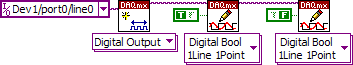
Have you gone over the shipping examples to understand how to output data with the DAQmx functions?
p.s. I forgot to connect the error in/error out clusters. They should be connected when you do your program.
Message Edited by Dennis Knutson on 07-23-2008 07:57 PM
