- Subscribe to RSS Feed
- Mark Topic as New
- Mark Topic as Read
- Float this Topic for Current User
- Bookmark
- Subscribe
- Mute
- Printer Friendly Page
Using DAQ Channel Concurrenly
12-18-2007 06:51 AM
- Mark as New
- Bookmark
- Subscribe
- Mute
- Subscribe to RSS Feed
- Permalink
- Report to a Moderator
I bother you again. I connect two DAQmx Create Channel as serial in VI program, to make different configuration for a different channel. But when I run the VI program, all wavegraph show same signal. How I can correct my VI program so the wavegraph show signal that suitable with channel (ai0 or ai1) is chosen?
Ok. thank you
Best regards
Cornelius
12-19-2007 10:16 AM
- Mark as New
- Bookmark
- Subscribe
- Mute
- Subscribe to RSS Feed
- Permalink
- Report to a Moderator
Thank you for your explanation, I have modified my VI but I am confuse, where I can connect the second DAQmx Create Channel ?
I try connect two DAQmx Create Channel as serial, but all wave graph show same signal. Is it possible to control wavegraph, so each wavegraph show a signal suitable with channel (ai1 or ai2) that write in Physical Channel button in Front Panel? Would you correct my Vi please ?
Thank you very much.
Best Regards
Cornelius
12-19-2007 03:12 PM - edited 12-19-2007 03:12 PM
- Mark as New
- Bookmark
- Subscribe
- Mute
- Subscribe to RSS Feed
- Permalink
- Report to a Moderator
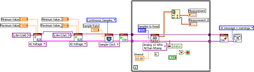
I can't view or modify your VI right now but here is a picture of a block diagram with multiple DAQmx Create Channels and the way to view them separately. Please not that you only need multiple DAQmx Create Channel functions if you are setting up different gains for each channel or if you are using different terminal configurations (i.e. diff or RSE).
Message Edited by Dennis Knutson on 12-19-2007 02:12 PM
12-20-2007 10:13 AM
- Mark as New
- Bookmark
- Subscribe
- Mute
- Subscribe to RSS Feed
- Permalink
- Report to a Moderator
Hi Dennis,
I made your diagram, and now i can see the signal at the wavegraph suitable with the physical channel is chosen.
Thank you very much for your attention and help.
Best regards
Cornelius
01-08-2008 06:40 AM
- Mark as New
- Bookmark
- Subscribe
- Mute
- Subscribe to RSS Feed
- Permalink
- Report to a Moderator
I am sorry, I bother you again.
I have tried to make a vi software to read 8 signal from DAQCard-6036E, and show each signal at 8 wavegraph. Each wavegraph is controlled by 8 physical channel. I have do what you suggest at your email later. And I try to acquisition signal using the DAQCard. After I do observation about the display, I think the wavegraph show the same signal. Could you help me to solve my problem. I attach my vi file, i hope you would correct my vi program.
Thank you very much for your help.
Regards
Cornelius
01-08-2008 06:42 AM
- Mark as New
- Bookmark
- Subscribe
- Mute
- Subscribe to RSS Feed
- Permalink
- Report to a Moderator
I am sorry, I bother you again.
I have tried to make a vi software to read 8 signal from DAQCard-6036E, and show each signal at 8 wavegraph. Each wavegraph is controlled by 8 physical channel. I have do what you suggest at your email later. And I try to acquisition signal using the DAQCard. After I do observation about the display, I think the wavegraph show the same signal. Could you help me to solve my problem. I attach my vi file, i hope you would correct my vi program.
Thank you very much for your help.
Regards
Cornelius
01-10-2008 08:39 AM
- Mark as New
- Bookmark
- Subscribe
- Mute
- Subscribe to RSS Feed
- Permalink
- Report to a Moderator
Hi Cornelius,
Can I ask if you have all your signals connected to the analog inputs of you DAQ card and if they are grounded properly? The code you attached should run fine. However, when I only connected one input, while you would expect to see the first graph change and the rest remain at zero, I noticed that the other graphs followed my one input.
This could be a sign of ghosting, i.e. when the analog to digital convertor (ADC) cycles through the input channels so fast that it has no time to drain off retained voltages and therefore readings from later channels reflect those already read. The Knowledge Base Document 3L8IETLO: How Do I Eliminate Ghosting From My Measurements? has an excellent explanation of ghosting and suggestions for how to keep ghosting from affecting your readings.
I would suggest connecting all your signals, properly grounding your breakout box if you have one, and lastly possibly using a bias resistor between each of the signals and ground, as can be seen in Differential or Single Ended Non-Referenced intersection with Floating Source entry of Table 1 from the Developer Zone Article: Field Wiring and Noise Considerations for Analog Signals.
I hope this explanation helps, Mallori M.01-11-2008 06:38 AM
- Mark as New
- Bookmark
- Subscribe
- Mute
- Subscribe to RSS Feed
- Permalink
- Report to a Moderator
Thank you for your explanation, i will try to do your solution.
Best Regards
Cornelius
01-16-2008 04:38 AM
- Mark as New
- Bookmark
- Subscribe
- Mute
- Subscribe to RSS Feed
- Permalink
- Report to a Moderator
01-16-2008 08:28 AM - edited 01-16-2008 08:29 AM
- Mark as New
- Bookmark
- Subscribe
- Mute
- Subscribe to RSS Feed
- Permalink
- Report to a Moderator
Hi Cornelius,
You can make the values in a drop down box the default by right-clicking on the box on the front panel, selecting Data Operations, and then Make Current Value Default. This means, that while the values can be changed manually by typing in or selecting another value from the drop down menu, the value that you set to default will be the saved value that is present when the VI is opened.

If, however, you meant that you wanted the channels to be a constant since you will always be reading from those channels, then what you could try is placing a channel constant down on the block diagram and wiring it to the DAQmx Create Channel’s physical channel terminal. You could then right click on the wire between the constant and the function and then select Create >> Indicator which will then place an indicator on the front panel that allows you to see what channel is being read. You can still change the channels but this must be done from the block diagram. This can be seen in the second image.

Good Luck, Mallori M.
Message Edited by mallorim on 01-16-2008 08:29 AM
