- Subscribe to RSS Feed
- Mark Topic as New
- Mark Topic as Read
- Float this Topic for Current User
- Bookmark
- Subscribe
- Mute
- Printer Friendly Page
simultaneous digital output line and analog data acquisition?
02-08-2006 01:36 PM
- Mark as New
- Bookmark
- Subscribe
- Mute
- Subscribe to RSS Feed
- Permalink
- Report to a Moderator
02-08-2006 05:35 PM - edited 02-08-2006 05:35 PM
- Mark as New
- Bookmark
- Subscribe
- Mute
- Subscribe to RSS Feed
- Permalink
- Report to a Moderator
Hi Greg,
NI-DAQmx will make this problem quite simple. There are a number of signals associated with analog input tasks that can be "exported". You can use the DAQmx Export Signals.vi (see image) to export these digital signals to the PFI lines on your device. You might want to check Measurement and Automation Explorer (MAX) for the available signal routes (not all signals can be routed to all PFI lines). In MAX, select your device, under NI-DAQmx Devices and click the Device Routes tab.
Depending on what signal you need for your external device, you have some options. The "Start Trigger" will give you a rising edge (logic 0 to 1 transition) at the beginning of the acquisition. The "Sample Clock" will give you a rising edge at the beginning of each sample. The "AI Convert Clock" is the signal that controls the multiplexing of multiple input channels to the ADC. So if you have 4 channels in your scan list, then you will get 4 rising edges per sample clock period.
It sounds like you might want to use the "Sample Clock" option, which in your case, will give you 1000 edges at 200kHz, of course, synchronized with your analog input samples.
-Alan A.

Message Edited by Alan [DE] on 02-08-2006 05:35 PM
02-08-2006 07:46 PM
- Mark as New
- Bookmark
- Subscribe
- Mute
- Subscribe to RSS Feed
- Permalink
- Report to a Moderator
Alen, that was awesome!
It worked perfectly! I've never used the mx VI's before, did not even know the power that existed with those things. Thank you so much for your help!!!
11-09-2007 10:08 AM
- Mark as New
- Bookmark
- Subscribe
- Mute
- Subscribe to RSS Feed
- Permalink
- Report to a Moderator
Hello,
I've been spending most of today trying to do something similar but with no success. I need to collect 129 samples and output both the sample clock and the start trigger. I've tried using both the DAQmx Export Signals and Connect Terminals VIs but get nothing coming out the selected PFI terminal and no error messages. With the Export Signals VI I am putting it between the clock VI which sets up the task timing and the start VI, setting the input as 'sample clock' and the output as 'dev1 PFI9'. Whenever I run the program though the output stays low.
The only example I could find similar to what I'm trying to do is the 'Pulse train generation for AI sample clock' but this appears to output the sample clock without using either the Export or Terminals VIs. I don't really understand what's going onin this one or how I might be able to extend it to include a pulse when acquisition starts.
According to MAX I should be able to route the signals on the card I'm using (PCI-6010) as I am trying to do.
Thanks in advance,
Simon.
11-12-2007 09:00 PM - edited 11-12-2007 09:04 PM
- Mark as New
- Bookmark
- Subscribe
- Mute
- Subscribe to RSS Feed
- Permalink
- Report to a Moderator
Hi Simon,
Thanks for contacting National Instruments. If I understand your problem correctly, you want to use your PCI-6010 card to acquire 129 samples, while outputting the “Sample Clock” on one PFI line and the “Start Trigger” on a second. However, you have placed an Export Signal.vi between the Sample Clock and Start Task.vis of your program and still do not see any digital output on the specified PFI line. Is this assessment correct? If not, could you please clarify?
The example VI you mentioned in your post, 'Pulse train generation for AI sample clock,' is actually generating a digital pulse train that the analog input task would then use as a sample clock, instead of a provided external clock. It sounds, however, like you want to export the sample clock that is already provided and that the analog input is using. Therefore, you are correct in believing that this example VI is not appropriate.
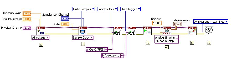
I was unsure, however, as to how your entire program was set up. I am including a screen shot of the example “Acq&Graph Voltage-Int Clk” VI that I have modified to suit your purposes and tested on my computer to ensure that it works. Note that my PCI card is Dev 2, not Dev 1, as yours is. I included in the program an Export Signal.vi where you indicated placing one yourself.
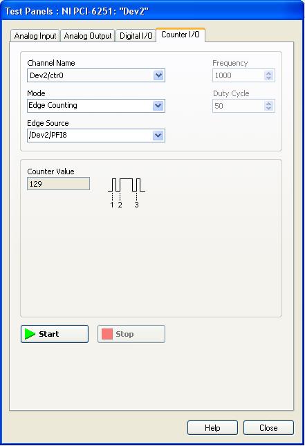
In order to test the program, I opened a test panel in MAX for my PCI card, selected the Counter I/O tab, and set the controls as seen in the attached screenshot. By Starting the Test Panel, and then running the LabVIEW program, I was able to record the rising edges of the Sample Clock being exported on PFI8. Similarly, when I tested the Start Trigger’s PFI, the event count increased by one.
Your PCI-6010 can support the Start Trigger and Sample Clock on PFI lines 6-9, so any of these channels can be selected for the exported signals. Can I ask how you are testing if the line has gone high?
I hope that this helps you achieve the functionality you are looking for. If you have any further questions, feel free to post back. Thanks-
Mallori M
Message Edited by mallorim on 11-12-2007 09:04 PM
11-14-2007 05:37 AM - edited 11-14-2007 05:40 AM
- Mark as New
- Bookmark
- Subscribe
- Mute
- Subscribe to RSS Feed
- Permalink
- Report to a Moderator
Dear Mallori M,
Thanks very much for your detailed reply. Yes your understanding of what I am trying to do is correct (I'm actually trying to read a linear diode array which needs a pulse to switch to the next diode before each sample).
I tried running the VI example you give above but unfortunately it produced the same lack of response (I'm using a 100MHz oscilloscope between the digital ground and the PFI line). I then tried the test panel in MAX using counter 0. When I selected PFI 8 and clicked on the start button it immediately brought up and error (number 89136) which said that the hardware did not support that route. I tried various other options in the 'edge source' list to see what would happen and got the same error for PFI lines 6 to 9. Lines 0-5 did not give an error and choosing the start trigger or sample clock options in the list then running the Labview VI gave the expected response.
I then had another look at the Routing table in MAX (see attached file) but this does defninately say that I can route the sample clock directly to PFI 6-9. It does however say that I can route the sample clock to PFI 0-5 which I remember brought up an error when I tried it in Labview. Do you know what might be wrong here?
Thanks,
Simon.
Message Edited by Simon GB on 11-14-2007 05:40 AM
11-15-2007 10:59 AM
- Mark as New
- Bookmark
- Subscribe
- Mute
- Subscribe to RSS Feed
- Permalink
- Report to a Moderator
Hi,
I've just tried monitoring the pulses using a bench top counter rather than a scope and can now see them on PFI 9. It appears that they were just too short and widely spaced to be seen on my scope (I had thought that they would increase in width as the sample rated reduced). Thanks again for your help.
Simon.
11-15-2007 12:00 PM
- Mark as New
- Bookmark
- Subscribe
- Mute
- Subscribe to RSS Feed
- Permalink
- Report to a Moderator
Hi Simon,
Glad to see that everything is working for you now. Feel free to post back if you have any further difficulties. Best of luck with your application.
Thanks-
Mallori M
