- Subscribe to RSS Feed
- Mark Topic as New
- Mark Topic as Read
- Float this Topic for Current User
- Bookmark
- Subscribe
- Mute
- Printer Friendly Page
Engine Simulation Custom Device Feedback
07-25-2013 12:37 PM
- Mark as New
- Bookmark
- Subscribe
- Mute
- Subscribe to RSS Feed
- Permalink
- Report to a Moderator
Great idea. I just implemented this and am about to build. Do i need the APU.Reset connected to every new APU block i created in the angle progessing loop?
James.
07-25-2013 12:40 PM
- Mark as New
- Bookmark
- Subscribe
- Mute
- Subscribe to RSS Feed
- Permalink
- Report to a Moderator
Oh yeah. Yes you do.
07-30-2013 12:24 PM
- Mark as New
- Bookmark
- Subscribe
- Mute
- Subscribe to RSS Feed
- Permalink
- Report to a Moderator
Works great, Thanks Steven...
Oh i was wondering is there a link to the plant model thats used in Driven? I was looking to set up a basic plant model on the HIL as a starting point.
I could maybe compile the driven labview code into a DLL and run it.
James
07-31-2013 09:31 AM
- Mark as New
- Bookmark
- Subscribe
- Mute
- Subscribe to RSS Feed
- Permalink
- Report to a Moderator
Great!
Im not personally familiar with a Drivven plant model of an engine. There may be one but I would ask them directly if you have a contact with them.
In the past I've used a plant model from ITI's SimulationX.
07-31-2013 03:42 PM
- Mark as New
- Bookmark
- Subscribe
- Mute
- Subscribe to RSS Feed
- Permalink
- Report to a Moderator
Ok great. Now that my HIL i/o is looking good i now want to upgrade to your new version 3.7 veristand 2012 custom device, I'm currently running v3.6.
What is the best way to upgrade to minimise risk to my HIL setup?
I'm guessing i install the files into the existing "C:\Users\Public\Documents\National Instruments\NI VeriStand 2012\Custom Devices\Engine Simulation"
Do i then need to do a rebuild of my labview code and use the new bitfile created?\
I could create a new folder called "Engine Simulation 3.7" hence allowing me to revert if there is an issue.
Will the custiom device still run with a different root file name?
James.
07-31-2013 03:54 PM
- Mark as New
- Bookmark
- Subscribe
- Mute
- Subscribe to RSS Feed
- Permalink
- Report to a Moderator
In reference to above, i went ahead and installed the v3.7 custom device. i saw a 50% improvement. My ES loop count Duration went down to 0.5 ms from 1 ms. By removing some signals its now at 0.4 ms.
thanks,
James
08-06-2013 09:05 AM
- Mark as New
- Bookmark
- Subscribe
- Mute
- Subscribe to RSS Feed
- Permalink
- Report to a Moderator
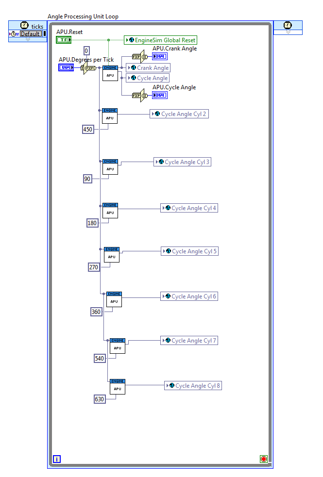
I'm looking at using the engine simulation device to do some testing of one of our ECU's. The challenge I'm running into right now is to seperate out a "batched" spark pulse. On our engine controller we have a double ended coil on one spark output of the ecu. Each end of the coil goes to a cylinder (in this case cyinders 1 and 4). I want to be able to tell which spark pulse goes with which cylinder. As a simple test I just added a true / false check on the encoder angle to say that if the encoder was greater than 360 degrees then it would be true and I would save the end angle as IC 9, if it was true i'd save the end angle as IC 4 (screen shots below).


After I delployed this FPGA code, my Veristand workspace variables for IC 4 and IC 9 end angles still dithered between the two different end angles.
Do you have any suggestions on how to make something like this work? The debug pin is filpping between true and false every 360 degrees, the end angle for IC 4 is 271 degrees and the end angle for IC 9 is 631 so I would have expected this to work.
(Sorry if there is any confusion on why i named it IC 9, i just wanted to use something I knew was out of the way and would show up in the custom device).
Here is a scope screen shot showing the two IC (named on the scope EST) pulses against a 60-2 encoder.

09-27-2013 06:08 AM
- Mark as New
- Bookmark
- Subscribe
- Mute
- Subscribe to RSS Feed
- Permalink
- Report to a Moderator
Dear Colleagues,
I have to develop a proposal for a customer that needs Engine Sensors Simulation (crankshaft and camshaft signals) and AES library is very valuable for simulating 0-Vbat (i.e. 12V)
signals but I also have to provide support for VRS sensors, that the ECU (devide under test) acquires by means "zero crossing" detection:
- it's allowed generating on/off signals (instead of more complex analog waveforms)
- those signals have to be "zero crossing"
I should think of using NI 9263 analog outputs, but the AES library is based on Single Cycle Timed Loops and the software architecture has to be dramatically changed in order to support analog generation:
- do you have resources/solutions to propose to my customer?
- zero crossing can theoretically be afforded by NI 9505 (H-bridge), is it correct? Can you please help me in validating this proposal and adapting the sample library?
Do you see any drawback (other than higher cost and single channel per module?). Is there any simpler solution, like an external electronic component I can drive by either NI 9474 or NI 9401?
Thanks so much
ciao
09-27-2013 11:19 AM
- Mark as New
- Bookmark
- Subscribe
- Mute
- Subscribe to RSS Feed
- Permalink
- Report to a Moderator
Hi Wolverine,
I have great news. We have developed an update to the AES library and Engine Simulation Custom Device for arbitrary data file replay from analog outputs. Perfect for VR sensors. It is in beta now and I will email you the beta to try out.
10-16-2013 05:30 PM
- Mark as New
- Bookmark
- Subscribe
- Mute
- Subscribe to RSS Feed
- Permalink
- Report to a Moderator
Hi Stephen,
reference: 150. Jul 19, 2013 10:17 AM (in response to jamesy)
I am now at a fine tuning stage of HIL bench development. i still have the 1 degree error which i want to remove.
The actual TDC from the customer is definded as: 283 degrees before the first falling edge AFTER the gap is detected.
This translates to 283-18 = 265 degrees. ( when begininning of Gap is selected.)
Veristand settings:
Missing teeth after TDC is 265 degrees.
Tooth / Gap duty cycle == 50
no of teeth 60.
no of missing teeth = 2
When i look at the ECU commanded actuator values they read: SOI 348 EOI 324
Veristand measured values : SOI 347 EOI 324.9
All measured values are off by one degree.
So the obvious solution is to move "Missing teeth after TDC is 265 degrees" plus or minus one.
When i do this, i see no change. Everything is still off by 1 degrees.
I am guessing that the problem is how the system calculates the missing teeth. It is not possible to define TDC position in veristand +/- 1 degree.
Do you have a solution other than me adding/removing 1 degree later in a calculated channel ?
