- Subscribe to RSS Feed
- Mark Topic as New
- Mark Topic as Read
- Float this Topic for Current User
- Bookmark
- Subscribe
- Mute
- Printer Friendly Page
Example of Embedded C-Code Integration in a Multisim Power Electronics Co-Simulation of a Boost Converter
11-07-2012
05:18 PM
- last edited on
10-13-2025
01:11 PM
by
![]() Content Cleaner
Content Cleaner
- Mark as New
- Bookmark
- Subscribe
- Mute
- Subscribe to RSS Feed
- Permalink
- Report to a Moderator
In this example, I compile the simple C code for a boost converter proportional (P) voltage regulator into a DLL and use Multisim co-simulation to test it.
Here is the boost converter circuit I will control using the proportional regulator written in C-code. A 5 kHz PWM signal is used to gate a Vishay IRFD110 N-Channel Power MOSFET, along with an ON Semiconductor MBR10H100CTG 10 A, 100 V H-Series Schottky Rectifier
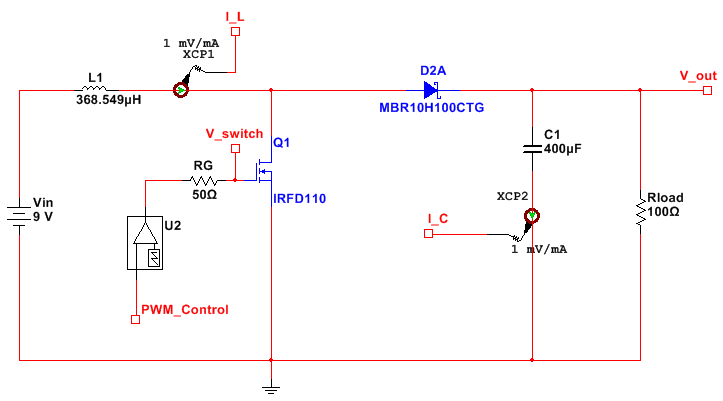
First, I followed the LabWindows/CVI instructions in these help docs to convert the C code to a DLL for calling in LabVIEW.
Tutorial: Creating a LabWindows/CVI DLL to Use on a LabVIEW Real-Time Target
Here is the C code in LabWindows/CVI, ready to be compiled to a DLL that can be called by LabVIEW for co-simulation with Multisim.
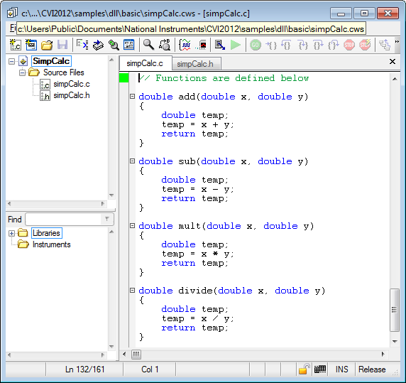
A header file is created as described in the tutorial linked above. The Target Settings are configured as shown below.

Note:
- The generated DLL can be executed on any LabVIEW Real-Time Pharlap OS target, such as the Multicore CompactRIO. LabWindows/CVI does not compile to executables for VxWorks Real-Time Operating System targets such as the sbRIO-9606 General Purpose Inverter Controller. You will need to use an appropriate VxWorks C Compiler. For more information about compiling C code to VxWorks targets like the NI GPIC see, this application note:
Developing Shared Libraries for the cRIO-901x and Other VxWorks Targets
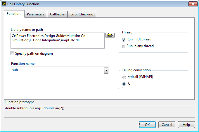
Next, I create a LabVIEW subVI to contain the DLL calls, place down a Call Library Function and select the C code DLL I generated (simpCalc.dll) and the subtract (sub) function.
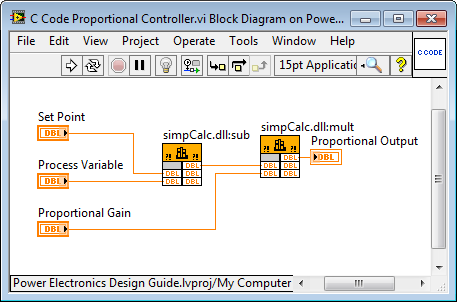
The result is this subVI with two calls into a DLL routine. One performs a subtract (sub) function and the other performs a multiply (mult) function. I wire up these function calls to create a simple Proportional controller, whereby:
Proportional Output = (SetPoint-Process Variable)*(Proportional Gain)
Here is the Multisim power electronics schematic for the boost converter.
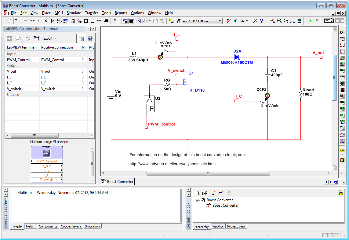
Then I add my proportional control regulator written in C code to my Boost Converter example from the Power Electronics Design Guide to regulate the voltage. Obviously there is going to be some steady-state error since there is no Integral gain in the control compensator. But it works well as you'd expect of a proportional (P) only controller.
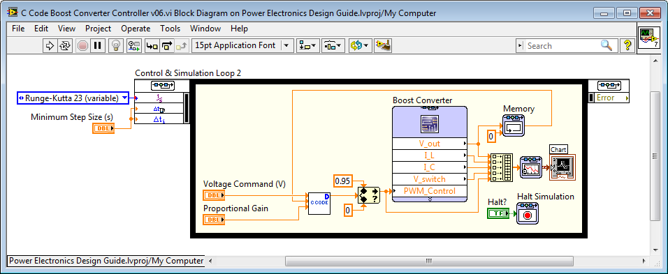
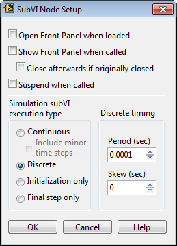
To set the execution loop rate that the C Code will execute on the embedded target, right-click on the subVI and go to SubVI Node Setup. Set the execution type to Discrete and type in the execution Period (sec). Note the D glyph in the upper right corner of the subVI that indicates it is a discrete subVI. The LabVIEW Control & Simulation Module will execute it at the appropriate discrete time interval during simulation.
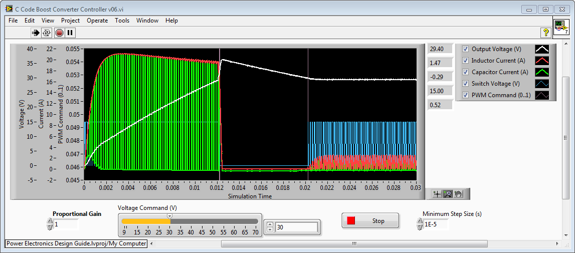
Here is the response to a step command setpoint of 30 Volts. As I'd expect, the voltage regulator overshoots and then settles below the setpoint. In this case, the steady state error is 0.6 Volts.
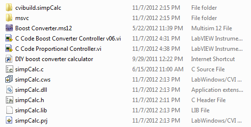
The LabWindows/CVI, LabVIEW and Multisim code is attached. Here is a screenshot of what's contained in the ZIP file.
Note:
- Text based HDL code can also be integrated into co-simulation applications. You will first need to generate an HDL simulator testbench as described in the application note below. Then you can embed the HDL Interface Node containing the testbench simulation capabilities into your co-simulation application in a similar manner to the way the C code DLL calls were embedded in the LabVIEW Control Design & Simulation loop as described above.
