- Document History
- Subscribe to RSS Feed
- Mark as New
- Mark as Read
- Bookmark
- Subscribe
- Printer Friendly Page
- Report to a Moderator
- Subscribe to RSS Feed
- Mark as New
- Mark as Read
- Bookmark
- Subscribe
- Printer Friendly Page
- Report to a Moderator
Contact Information
University: Carnegie Mellon University
Team Member(s): Matt Eicholtz, David Chang, Balu Nair, Sai Yamanoor
Faculty Advisors: Dr. John Dolan, Dr. Charles Neuman
Email Address: mattheweicholtz@gmail.com
Project Information
Title: Connect Four Player
Description: We have built a mechatronic device capable of playing the game of Connect Four against a human or robot player. The machine sorts and dispenses chips with greater than 99% accuracy, executing moves in 8 seconds on average.
Products:
NI LabVIEW 2010 with Embedded Module for ARM Microcontrollers
Stellaris ARM LM3S8962 Evaluation Board
NXP1768-based MBED Microcontroller
The Challenge:
This project was completed to fulfill the requirements for a course on Mechatronic Design at Carnegie Mellon University. The basic premise of the project was to design and build a system that can efficiently play Connect Four against an opponent. There were restrictions on size (approximately 36" x 22" x 36", W x D x H), and the device had to be portable, using a dedicated power supply for electronics.
To prepare the machine for gameplay, the chips could either be dumped into a container in the machine or stacked on the playing surface to be picked up by the machine. The required performance metrics included:
1. The mechanism must be able to insert game chips into all 7 slots in the board.
2. The mechanism must take no more that 20 seconds per move.
3. The mechanism must retract from the neurtral area (12" x 8" area surrounding board) between turns.
4. The mechanism must display some level of game-playing intelligence (i.e. no random moves).
5. The mechanism must transmit its moves to the opponent via rs232 serial protocol (9600 baud rate, no parity, 8 bits per message, 2 stop bits, no flow control).
The Solution:
(For a more detailed description of how our system works, see the report attached at the bottom)
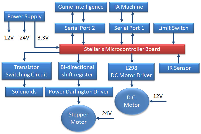
For our design, we wanted to minimize the number of subsystems, the actuated degrees of freedom (DOF), and the dependence between subsystems. Therefore, the concept we selected (shown below in Figure 1) has two mechanical subsystems, a chip sorter and a chip dispenser, that interface at one location and each have one actuated DOF. The primary microcontroller is a Stellaris ARM LM3S8962, although we use a separate MBED board for game intelligence. The artificial intelligence is modified from open source code and looks several moves ahead to determine the best move.

Figure 1: CAD assembly of machine
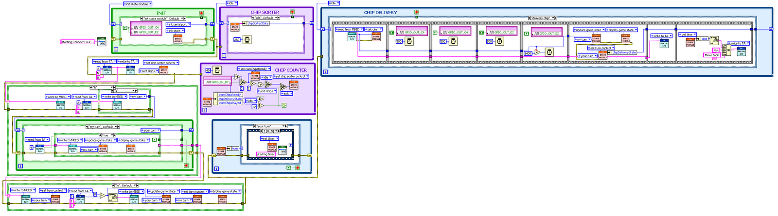
Figure 2 illustrates the sequence of events that our system performs to achieve the aforementioned game objectives. The red and green dotted rectangles represent the chip sorter and chip dispenser, respectively.
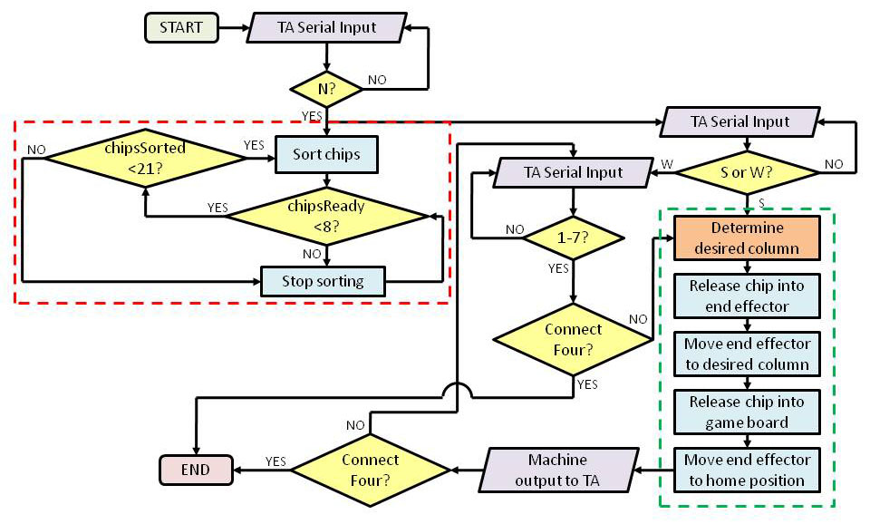
Figure 2: Operational flowchart
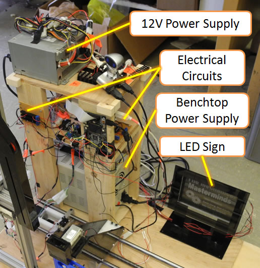
As shown in Figure 3, we have categorized our overall system into four areas: the chip sorter, the chip dispenser, the electrical circuits, and the control code (not shown in the figure for obvious reasons!).
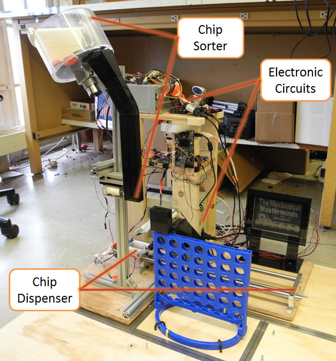
Figure 3: Final implementation of overall system
Chip Sorter
Chips poured into the chip sorter are organized into a column of vertically-stacked chips. Figure 4 is labeled with the terms that will be used to describe the sorter parts. The hopper is tilted such that chips are collected on one side, oppositeof the chute. A 3D-printed plaster piece placed on the hopper wall ensures chips eventually fall flat onto the rotator. A 12V DC motor spins an acrylic rotator which carries chips up to the chute opening. The rotator has a circular cutout on the edge for a single chip to fit into. An acrylic piece is glued to the hopper wall near the chute opening to ensure that only one chip falls into the chute at a time. An IR slot sensor near the top of the chute detects when the chute is full so the DC motor can be stopped. A chip is released into the end effector of the dispenser via a solenoid. Since the support structure is made of 80/20 extruded aluminum, both the hopper and solenoid have adjustable positioning in all three dimensions, allowing for easy alignment of the chute over the end effector.
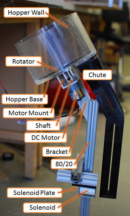
Figure 4: Chip sorter
Chip Dispenser
Upon receiving a chip from the sorter, the dispenser delivers the chip to the appropriate column. The main mechanical components for this subsystem are outlined in Figure 5. A 24V, unipolar stepper motor drives the system and is connected to a precision lead screw via a flexible spring-beam coupling. In this way, rotation of the motor is converted to translation of a linear carriage. A rigid, acrylic structure is mounted to the carriage base and positions the end effector above the height of the game board. When the end effector is located above the correct column, the chip is released into the board using a solenoid, which is shown in Figure 6. To reduce frictional effects and backlash, the carriage position is zeroed at the end of each turn using a limit switch. The linear carriage is supported by two steel rods, and the lead screw is supported by ball bearings mounted in the side brackets.
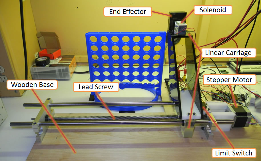
Figure 5: Chip dispenser
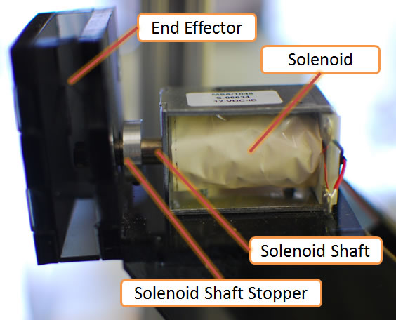
Figure 6: End effector

- Mark as Read
- Mark as New
- Bookmark
- Permalink
- Report to a Moderator
Hello there,
Thank you so much for your project submission into the NI LabVIEW Student Design Competition. It's great to see your enthusiasm for NI LabVIEW! Make sure you share your project URL with your peers and faculty so you can collect votes for your project and win. Collecting the most "likes" gives you the opportunity to win cash prizes for your project submission. If you or your friends have any questions about how to go about "voting" for your project, tell them to read this brief document (https://forums.ni.com/t5/Student-Projects/How-to-Vote-for-LabVIEW-Student-Design-Projects-doc/ta-p/3...). You have until July 15, 2011 to collect votes!
I'm curious to know, what's your favorite part about using LabVIEW and how did you hear about the competition? Great work!!
Good Luck, Liz in Austin, TX.
- Mark as Read
- Mark as New
- Bookmark
- Permalink
- Report to a Moderator
Great Work , All the best
- Mark as Read
- Mark as New
- Bookmark
- Permalink
- Report to a Moderator
Hardwork and self confident leads to victory only go ahead, all the best...........
“The only thing that overcomes hard luck is hard work.” ~ Harry Golden
- Mark as Read
- Mark as New
- Bookmark
- Permalink
- Report to a Moderator
Great Accomplishment!!! Good Luck Guys
