- Document History
- Subscribe to RSS Feed
- Mark as New
- Mark as Read
- Bookmark
- Subscribe
- Printer Friendly Page
- Report to a Moderator
- Subscribe to RSS Feed
- Mark as New
- Mark as Read
- Bookmark
- Subscribe
- Printer Friendly Page
- Report to a Moderator
Contact Information
Competition Year: 2017
University:Delft University of Technology
Team Members (with year of graduation): Debarghya Ghosh (2015), Simeon Castle (2015)
Faculty Advisers:Manuel Mazo
Email Address:tinnichat@msn.com
Country: NL
Project Information
An annual synthetic biology competition involving 250 universities worldwide known as iGEM led to this work. TU Delft participated in iGEM. The team decided to genetically modify an off-the-shelf Escherichia coli (E. coli) bacteria and make it sensitive to explosive compounds such as TNT and DNT. The team intended to modify the bacteria such that in the presence of explosive materials, it would eject a constant stream of electrons, in other words, an electric current. The final practical application would be to produce a low-cost land mine detector, which would be light and handy to transport. The final device could be placed into the soil where landmines might exist, and if that was the case, the device containing the bacteria would eject electrons. The team needed to develop relevant instrumentation to detect this ejected current and eventually notify a buzzer to create a sonic alert.
Figure1: The e-coli bacteria
Electrace: Using E. coli Bacteria to Develop a Low-Cost Landmine Detector
Products: NI myDAQ , LabVIEW
The Challenge: Developing an instrument to measure the electrical signals emitted by E. coli bacteria when exposed to explosive compounds to eventually create a low-cost land mine detector that is light and easy to deploy.
The Solution: Using NI LabVIEW software and NI myDAQ, we developed a cheap, effective, and accurate potentiostat, capable of measuring our E-Coli signals, and saving us thousands of dollars.
Motivation Behind Device Development
I had the task of developing the appropriate instrumentation for detecting and quantizing the current as ejected by the bacteria upon exposure to TNT and DNT compounds, in addition to building a suitable configuration that could house the bacteria. Electrochemists typically use a device that does this kind of task to precisely measure electrons as ejected by various electro-chemical reactions. This device is called a potentiostat. Using a potentiostat may cost many thousands of dollars. We wanted to develop an alternative, which replicates the function of a potentiostat at a significantly cheaper price.
We used an NI myDAQ device in conjunction with circuitry we designed to emulate a potentiostat. We found the myDAQ combined withLabVIEW software extremely useful as we could measure the current detected by the electrodes and display it in close to real time. Moreover, we took advantage of the graphical programming nature of LabVIEW to efficiently program the software part purely based on intuition, without any prior programming knowledge. We utilized charts and graphs to effectively record the acquired data and save this into files for future analysis. We used the myDAQ for data capture and to alter the voltage applied to the bacterial solution for effective detection purposes.
Figure 2: The developed device in operation
The Device: An Inexpensive, Effective, and Accurate Potentiostat
The Hardware
The potentiostat is the hardware required to control a three-electrode system used for the analysis of electrochemical experiments. The system consists of three separate electrodes: the working electrode (WE), reference electrode (RE), and the counter electrode (CE). Figure 3 illustrates the generalized cell configuration of such a system. We used operational amplifiers in various negative feedback configurations to replicate the functioning of a potentiostat.
Figure 3. Cell Configuration of the System
We applied a varying potential to the WE with respect to the RE; hence, the electrons that were ferried out into the sample by the E. coli resume motion under the effect of the applied electromotive force. The CE can now detect the generated current and relay the information to the PC through the myDAQ. We again applied this varying potential that works as the force pushing the emanated electrons using the PC through the myDAQ.
The associated circuitry consists of both digital and analogue elements, which are required to effectively transmit the measured data to a PC. We used the myDAQ in conjunction with the designed analog circuitry as the myDAQ already possesses a built-in A/D and D/A converter, so the user only needs to connect the wires from the analog domain into suitable ports of the device. This was a crucial positive aspect of the myDAQ that truly simplified the device construction. Someone with limited knowledge of digital electronics can very easily use a myDAQ for a specialised purpose.
We segregated the hardware into various modules:
- Voltage adder (summing device)
- Polarity inverter
- Voltage buffers (load-independent voltage regulators)
- Cell components (WE, RE, and CE)
- myDAQ/myRIO—A/D and D/A converters interfacing with PC (USB and LabVIEW)
Figure 4. Simplified System Diagram
As mentioned, the core idea of a potentiostat is to excite the WE with an external voltage to generate the electromotive force that can push the transported electrons into the counter electrode. Due to the availability of software like LabVIEW, we can generate any waveform and then apply it through the myDAQ on the electrode (WE).
Prior to application, the voltage summer ensures that the applied voltage at the WE is with respect to the electrochemical ground as measured by the RE. Due to disturbances in the physical electrochemical cell itself, the electrochemical ground from the reference element RE as well as the actual output of the voltage summer to be applied to the working electrode WE might fluctuate. A buffer reduces noise and interference from external sources.
Once we push the electrons into the CE, the current generated is to be sensed. The current first passes through a current–to–voltage convertor, and is subsequently digitized through the myDAQ and relayed to the PC screen almost instantaneously.
The Software
Once we have digitized the signals, we must chart the acquired signals on a graph in the signal (voltage/current) versus time format in almost real time. To achieve this, we used LabVIEW.
LabVIEW provides an advantage over other conventional script-based programming software like C as it works on graphical code. Users just need to have the logic ready in their minds, which they can then easily implement by dragging and dropping various functional blocks and interconnecting them through wires. These wires establish the signal flow within the digital domain in a software setting.
The DAQ Assistant blocks are the interface between the physical device and the software. We use two such assistants: one to generate the excitation signal and the other to sense the current and chart it on a graph.
Figure 5. Graphical User Interface, Developed in LabVIEW
The LabVIEW front panel contains the charts that display the sensed current and applied excitation. We use very efficient features like the knob, switches, and more to apply the required voltage on the WE and to emulate the front panel of a physical potentiostat device. We could also adjust other waveform settings like signal phase, amplitude, and frequency through suitable input options included on the front panel. The combination of suitable LabVIEW code and the myDAQ helps to emulate a potentiostat without the heavy price tag.
Experimental Results
We carried out a test experiment in which we compared the measured current with the expected mean current that should theoretically be detected. The results in Figure 6 show that the sensing is very accurate when the price to accuracy ratio is considered.
Figure 6. Experimental Results: Measured Current Versus Expected Current
We carried the test out with TNT solution injected into the modified E. coli, which was in the housing (also known as the microfluidic device) that we developed (Figure 7).
Figure 7. The Bacterial Housing, With Integrated Electrodes
We embedded all three electrodes within the housing and formed an integral part of it. Figure 8 shows the general testing procedure, where the analyte effectively constitutes the modified E. coli bacteria with other solutions that allowed the bacterial culture to remain healthy and alive.
Figure 8. The Testing Procedure
Future Steps and Goals
Next we plan to modify the design of the housing for practical usage in real-world settings, where users could simply insert the device into the soil with potential TNT content and obtain a suitable current reading. Furthermore, we want to develop a mobile app so readings can be viewed on a smartphone in real-time, with the data transferred to said phone through Bluetooth or WiFi. This aligns with our motivation towards building a plug-and-play portable biosensor system for the detection of landmines. From a biological standpoint, increasing the sensitivity of the organism to TNT/DNT would help us reduce the required sensing duration (currently four hours) to an instantaneous detection.
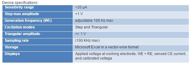
Figure 9. Device Specifications
Attach Poster

