- Document History
- Subscribe to RSS Feed
- Mark as New
- Mark as Read
- Bookmark
- Subscribe
- Printer Friendly Page
- Report to a Moderator
- Subscribe to RSS Feed
- Mark as New
- Mark as Read
- Bookmark
- Subscribe
- Printer Friendly Page
- Report to a Moderator
Etch-a-Sketch Project: Sketchy Business
Contact Information
University and Department: University of California Berkeley - Mechanical Engineering
Team Members | Faculty Advisor(s) |
Bernard Carreon | George Anwar |
Andres Hofmann |
|
Roy Lee |
|
|
|
Primary Email Address: andreshofmann@yahoo.com
Primary Telephone Number (include area and country code): 805-591-9950
Project Information
Please list all parts (hardware, software, etc) you used to complete your project:
Software:
· NI LabVIEW
· NI Vision
· ARM Module
Hardware:
· 2 Modified full-turn servos
· 2 Optical quadrature encoders
· 1 Luminary Micro Evaluation Board
· 1 Keil ULINK2 USB-JTAG Adapter
· 1 Breadboard
· 1 Etch-a-Sketch
· 2 Sets of pulleys and belts
Describe the challenge your project is trying to solve.
The original goal of this project was to modify a regular Etch-a-Sketch in a way such that we could load any picture on a computer, and this picture would be replicated on the screen of the Etch-a-Sketch.
In other words, the ultimate goal was to allow the user to select any standard image file using the GUI of our program. The computer would then process this file and then send the required motion control commands to the Etch-a-Sketch over a TCP/IP network.
Describe how you addressed the challenge through your project.
The challenge was successfully achieved by connecting two servos and two optical encoders to the knobs on the Etch-a-Sketch. By controlling each knob separately we were be able to locate and displace the drawing "pen" on the device to any location on the screen.
Software
We soon realized that creating an algorithm powerful enough to perform efficient shape recognition and calculate optimal route would require much more time than the one we had allotted for the project. The problem we had initially sought out to solve resembled the Traveling Salesman problem. A problem that is over 150 years old that involves combinatorial optimization and has not yet been solved. To work around this issue, we decided to try a different approach. The image processing algorithm would convert the input image into a shade intensity matrix. Intensities were mapped to a discrete values of shading or cross-hatching. The intensity matrix would later be converted into a set of PWM (Pulse-Width Modulation) commands that would later be streamed from the computer to the Luminary board using a client/server TCP/IP socket connection.
All the programming on both, the computer and the ARM micro-controller side was done using LabVIEW. LabVIEW made the implementation of the more difficult aspects of the project really simple. This is mostly due to the fact there are already a lot of built-in libraries for everything. For example:
- The code that creates the shade intensity matrix, the NI Vision module was very useful when dealing with images. Using NI Vision, we were able to iterate through an image to create a ROI and to take intensity values of an sub-image quite easily. We also used NI Vision to create the preview path of the Etch-A-Sketch.
- The TCP protocol library allowed us to communicate between the board and the PC. We initially tried using network variables, unfortunatelly that path had to be discarded due to its unreliability in establishing a stable connection over TCP/IP.
Hardware
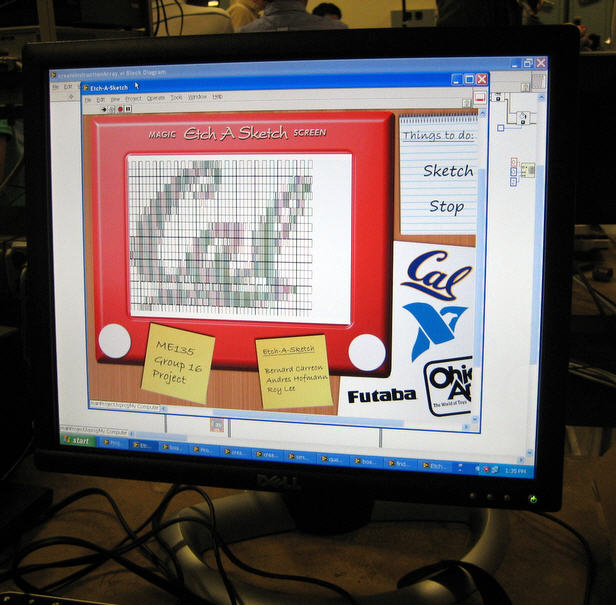
Through the use of two modified servo motors and two optical quadrature encoders we were able to reproduce the input image (i.e. the Cal logo as seen on screen). The servos were modified to allow a full 360 degree turn by sacrificing the built-in closed loop feedback functionality. This functionality was recovered by connecting two optical encoders directly to the output shaft of the servos.
A major challenge that we faced was the lack of "pen-up" functionality, meaning that due to the nature of the Etch-a-Sketch, the drawing must be continuous. In other words, once the computer starts drawing, all the following shapes will be connected by the same line.
One of the most unexpected and challenging obstacles that we faced in the development of the computer controlled Etch-a-Sketch, was having to compensate for the non-linearity nature of the drawing device. This non-linearity would manifest every time there was a change in direction in the drawing. As a consequence, error would accumulate very quickly as more and more was drawn on the screen. This problem was partially solved on the software side. Each time one of the servos would change directions, a compensation factor was applied to the motion.
Project web-site: http://sites.google.com/site/etchasketchsite/

