- Document History
- Subscribe to RSS Feed
- Mark as New
- Mark as Read
- Bookmark
- Subscribe
- Printer Friendly Page
- Report to a Moderator
- Subscribe to RSS Feed
- Mark as New
- Mark as Read
- Bookmark
- Subscribe
- Printer Friendly Page
- Report to a Moderator
High-speed Ultrasound Imaging System for Student Design Competition 2013
Contact Information
University:Beijing University of Technology (BJUT)
Team Members (with year of graduation): LIU Xingqi, XU Qinglong
Faculty Advisers: Prof. SONG Guorong, Prof. HE Cunfu
Email Address: xingqi1@139.com ; erjay2@126.com
Country: China
Submission Language: English
Project Information
Title: High-speed Ultrasound Imaging System based on NI FlexRIO
Description:
The invention is based on the platform of ultrasonic microscope, it has made a combination of FPGA and ultrasonic imaging technique, to achieve signal acquisition and processing by hardware technique. This design is differ from the traditional mode of C-scan, which using the “step-by-step” mode to achieve “point-to-point” measurement. We put forward a new scanning method to realize the high-speed ultrasound imaging, which means the probe donnot need to stop to wait for the signal processing completing, only let the FPGA do this work using its own clock . So in this way, the probe can run a the high speed to make the high-speed ultrasound imaging come true .
Products
Software:
NI LabVIEW 2011 Academic Standard Suite
· LabVIEW FPGA Module
· LabVIEW Motion Module
Hardware:
NI PXIe-1062
NI 8133
NI FlexRIO 7965R
NI 5734
NI 7344
The Challenge
Ultrasound imaging is an important way of nondestructive testing, it can help you know the internal information of the object without open or break it. So it becomes more and more popular in nowadays industry.
The traditional mode of C-scan, which uses ultrasonic information, is depended on “step-by-step” mode to achieve “point-to-point” measurement. They choose this way is mainly because:
The LabVIEW’s clock is depend on the operating system, which is on millisecond level, and the memory and processing rate of the computer is limited, when faces to a large mount of data run in the memory, so it is easily error. So they need write data of every step into hard disk. In this way, make a 300*300 points picture as an example, one second got one point in the test, it will takes 90000 seconds (25 hours) to get the whole photo. It is really a long time. So we need find a device to speed up the test without losing the precision.
The Solution
In order to speed up the testing, we bring FPGA technology into the ultrasonic microscope, use this hardware to deal the signal. As the clock of the FPGA is under microsecond level, the speed of the processing can raise over hundreds times.
The development of this new system can save the scanning time effectively , which the test time can be cut for over 95%. The new system can also provide a higher resolution and greater accuracy . So it can be widely used in dealing industrial problems.
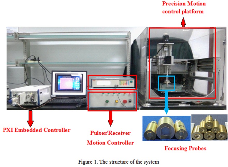
The system is constitute of PXI embedded controller, the precision motion control platform, PXI motion control board,signal acquisition board, FPGA board, oscilloscope, pulser/receiver, focusing probe, et al.
The system structure can be seen in Figure 1. The major controlling part of this system is NI 8133, which enables the control of the whole system, including the motion of the the precision motion control platform and complete collecting and processing of data got from the FPGA board to finish the ultrasonic imaging job.
The principles of this system:
Point-focus ultrasonic transducer generates and receives ultrasonic signals once it is excited by an impulse excitation. Then the signal are magnified and then be captured by PXI-5734 digital oscilloscope. The oscilloscope sends the magnified signal to PXIe-7965R for hardware signal processing. Features of the signal are transmitted by PXI buses to PXIe-8133 for a further imaging processing.
Meanwhile, PXIe-8133 controls PXI-7340 motion control board to finish the movement of scanning system so that probe can scan constantly while it is moving.
Introduction of system software
The system is worked in the cooperation of both host computer software and lower computer program. The lower computer program is used for collecting wave signals, while the host computer software is designed to accomplish interactive jobs, control movement and display images.
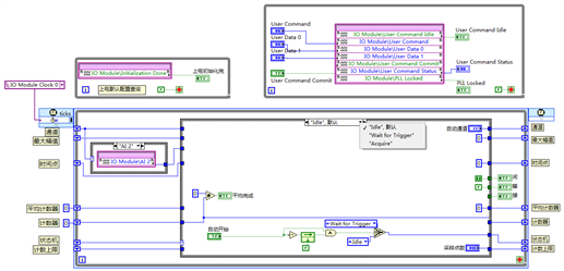
a) The Lower Computer Program
The lower computer program refers to NI PXIe-7965R, it is a FlexRIO FPGA module. The program starts to work once it has received a driving signal from the host computer. Then it makes a hardware level calculation of the waveform signals gathered by the front adapter module, picks up signal amplitude, time difference and other characteristic quantities and finally send the characteristic quantities to the host computer with the help of DMA.
The main part of the program is set in a single-cycle Timed Loop (SCTL) in order to achieve a faster execution, take less resource consumption and make a more determined execution time. The program uses a structure to combine SCTL and state machine to achieve switches in “idle”, “waiting trigger”,“capture”and other states. After power on the system enters an idle state, then program switches to the waiting trigger state after it has received a drive signal from the host computer. Every time a signal edge comes the program will be triggered to the capture state to get specified length of signal.The system has an inter set average function to reduce the influence of environmental noise. To take full advantage of the existing equipment resources, the system has a frequency as high as possible.And the system takes 120MHz signal from the adapter module PXI-5734 on-board crystal oscillator for FPGA clock so as to ensure that FlexRIO and adapter module have the same time for a more accurate data.
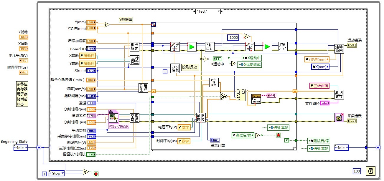
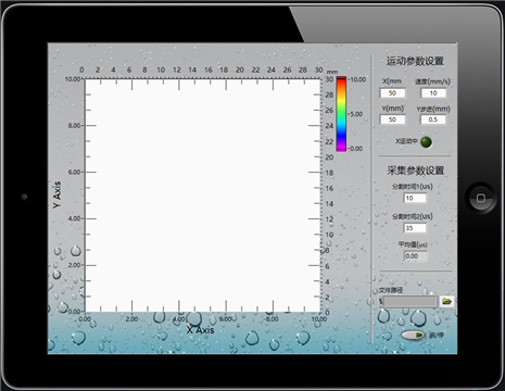
b) The Host Computer Software
The host computer software also adapts the structure of state machine. One of the basic functions of this software is motion control. On the one hand, it can guide the probe to act in a required routine, while on the other hand, when the program are interrupted it can stop the action of the probe and ask the prove to return to its initial position. There need only one adjustment for the initial position,so it is easy for operation.
While the probe is moving, characteristic quantities of waveform are read by the host computer,then the host computer works out the distance between the probe and the focusing point of ultrasonic wave. Image will be refreshed to reveal new features after every row scan.
In order to make the program diagram more concise, many sub VI are used in this program. Every sub VI is expected to accomplish one simple function,which have the advantages of low coupling and high cohesion. Besides, global variables are also used for data transfer because some sub VI can not transfer data between each other .
Results and some features of the device
Ø Surface Image
This test gives the results of the surface scan, our object is a penny. we also give out the picture of the real coin, to help you compare with our results. The table shows the parameters of this test.

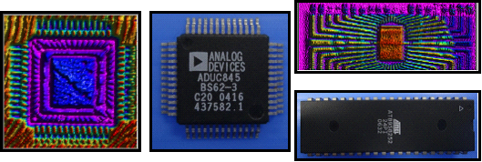
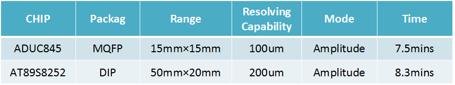
Ø Internal Face Image ( For Electronic Packing )
This test gives the results of the internal face scan, our object is two electronic components. In this test, we let the focusing probe focus on the inner layer of the electronic packing to get the circuit of the components. We also give out the picture of the real components, to help you compare with our results. The table shows the parameters of this test.
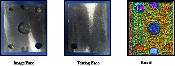
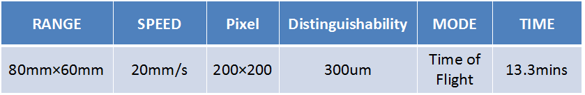
Ø The Reverse Side Image ( For Enclosed Construction )
This test gives the results of the reverse side image scan, our object is an aluminum block. In this test, we let the focusing probe focus on the testing face of object, but cut the signal of the bottom to imaging, in order to get the holes` image of the bottom. We called this test nondestructive examination. We also give out the picture of the real block, to help you compare with our results. The table shows the parameters of this test.
