- Document History
- Subscribe to RSS Feed
- Mark as New
- Mark as Read
- Bookmark
- Subscribe
- Printer Friendly Page
- Report to a Moderator
- Subscribe to RSS Feed
- Mark as New
- Mark as Read
- Bookmark
- Subscribe
- Printer Friendly Page
- Report to a Moderator
Overview:
This tutorial details how to build and play a novel musical instrument powered by the NI myDAQ--specifically a harp with LEDs/photodetectors in place of actual strings. The NI ELVIS II series may also be used, provided that modifications to the procedure and software are made.
Purpose:
Learn concpets behind photodetection and how to apply them to a useful application. LabVIEW signal acquisition and generation concepts are also presented.
Background:
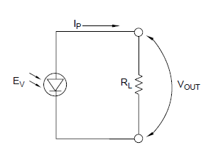
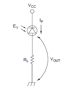
A photodiode has both an anode and a cathode. It has a low forward resistance (anode positive) and high reverse resistance (anode negative). Most photodiodes operate by negative biasing the anode or positive biasing the cathode. In the photovoltaic and zero bias modes, the generated current or voltage is in the diode forward direction. Hence the generated polarity is opposite to that required for the biased mode. Based on the type of photodetector you are using, different configurations of measuring light intensity exist. The following are two of the most common configurations at a basic level:
Figure 1: Fundamental Photodetector Circuit with Bias (left) and without Bias (right)
*Note that phototransistors can be substituted into the above circuits.
The LED harp uses a series of photodetector circuits without bias (shown on right in picture above) with a phototransistor subsituted for the photodiode. In addition to these topologies, photocurrent-voltage conversions can be made with opamps, and the gain can be amplified with various transistors. Once the circuit is created, the voltage can be read through a simple analog input port on the NI myDAQ or ELVIS II, and measured with LabVIEW or a Soft Front Panel (SFP) on the NI ELVISms Instrument Launcher. For more information on general light detection, refer to the "Measure Light Intensity" tutorial in the NI ELVISmx Instruments and Applications page.
Application:
The application demonstrated in this tutorial is a stringless harp. By lining up a series of infrared (IR) LEDs and phototransistors, we can create invisible “strings” that can be plucked just like a harp’s strings. There will be eight different IR strings that will be connected to the myDAQ’s eight digital lines. LabVIEW will detect which IR strings have been pulled and output the appropriate pitch through the Audio Out port of the myDAQ, or the Analog Out port of the ELVIS II. To increase the range of the instrument, we will add a button that increases the pitch by a half-step (for sharp and flat notes) and another button that will change the pitches between two octaves.
Equipment:
- NI myDAQ or ELVIS II series board
- Eight LEDs
- Eight Phototransistors
- Eight Small Resistors- ~100 Ω
- Ten Larger Resistors- ~1.2 kΩ
- Wires
- Two Button Switches
- 3.5 mm sub-miniature stereo socket (if using ELVIS II)
Set Up Hardware:
The figure below shows a portion of the LED Harp’s circuit. The phototransistors and LEDs continue on to the right so that there are 8 full sets of them (one for each digital line). The directions below can help you complete the circuit on the myDAQ or ELVIS II series board.

Figure 2: LED harp circuit diagram in NI Multisim
NI myDAQ Wiring Instructions
1. Plan ahead on your circuit. Make sure that you will have plenty of room for each of the infrared strings. A good layout is shown in Figure 3 below.
2. Place your first LED on your breadboard and wire its anode to the 5V power supply and its cathode to a small current limiting resistor. Then wire the other end of that resistor to ground.
3. Place your first phototransistor across from your LED and bend the two components so that the emitter is pointed directly at the detector (Figure 3 shows this).
4. Connect the appropriate end of the phototransistor to the 5V power supply and the other end to one of the larger resistors. Ground the other end of that resistor.

Figure 3: LED harp circuit on a protoboard
5. It is a good idea to test your first IR string before building the rest to make sure that you have the LED and phototransistor wired in the correct direction. To do this, launch the “NI ELVISmx Instrument Launcher.” It is found under Start>>All Programs>>National Instruments>>NI ELVISmx for NI ELVIS & NI myDAQ>>NI ELVISmx Instrument Launcher.

Figure 4: Scope location in the NI ELVISmx Instrument Launcher
6. Select the oscilloscope from the Instrument Launcher, shown above.
7. Connect the positive analog input 0 port [AI 0+] to the resistor/phototransistor junction (where the digital lines will be wired). Connect the negative analog input 0 port [AI 0-] to ground.
8. Click run on the oscilloscope. The oscilloscope should be showing a high signal (shown directly below).

Figure 5: Oscilloscope showing photodetector reading (LED open)
Try moving your hand between the LED and phototransistor to see if it drops the signal to a low value (again, shown directly below).

Figure 6: Oscilloscope showing photodetector reading (LED blocked)
If this isn’t working for you, make sure that the emitter and detector are aligned, try moving the LED closer to the emitter, and verify that the LED and phototransistor are wired in the correct direction.
9. After you have your first string working, wire the rest of them onto your breadboard.
10. Once all of the strings are wired, add one of the buttons to the breadboard. Connect one side to the 5V power supply and the other to one of the larger resistors. Connect that resistor to ground.
11. Wire the appropriate analog input’s positive port to the resistor/button junction, as indicated by Figure 2 above. Wire the negative port to ground.
12. Repeat steps 10 and 11 for the other button.
13. Finally, wire each of the digital lines to the appropriate phototransistor.
Your circuit should now be complete.
NI ELVIS II Series Wiring Instructions
The ELVIS instructions have an extra step, since there are no "Audio In" and "Audio Out" ports.
1. Complete all of the steps outlined for the myDAQ on the ELVIS II.
2. Connect the two terminals of a 3.5 mm sub-miniature stereo socket to AO0 and AGND.
Software Instructions:
As you can see, there are two different VIs included with this tutorial. The first version uses the DAQ Assistant Express VIs. These VIs are good because they are relatively easy to setup and use. The second version uses the low-level DAQmx VIs. These VIs are more efficient than the DAQ Assistants, but are thought to be more difficult to use. If your myDAQ is already “Dev1” (device 1) on your computer, you may not need to perform either of these procedures. If your myDAQ is not called “Dev1,” or if neither VI is working, try one of the setup instructions below. Additional instructions on how to use the ELVIS II board are shown at the bottom of this section.
Version 1: DAQ Assistants
The instructions below tell how to rename your myDAQ “Dev1” so that version 1 of the LED Harp VI will work.
1. Open the VI, “LED Harp Version 1.vi”
2. While your VI is open, open the “Measurement and Automation Explorer” by clicking on tools and select it from the top of the list that appears.

3. Next, find the devices that have been/are connected to your computer by navgating the tab tree on the left. My System>>Devices and Interfaces.

4. If your myDAQ is not the device called “Dev1”, delete that device by right clicking on the name and selecting delete, or rename it to something else.
5. Now, rename your myDAQ “Dev1” by right clicking on it and selecting “rename.”

The DAQ Assistants in the LED Harp VI should now be linked to your myDAQ, and the program should run.
Version 2: Low Level DAQ VI’s
To connect this VI to your instrument, the three task constants need to be reselected (if your myDAQ is not “Dev1”). Follow the steps below to accomplish this.
1. Open the VI and look at the block diagram.
2. Scroll over to the left side of the block diagram and find the three Task Constants.

3. For the task constant labeled “Audio Output,” simply click on the arrow on the right and select the audio output (left or right) for your device.

4. Next, click on the arrow for the task constant labeled, “Analog Input,” but this time, select “Browse…”

5. In the window that pops up, highlight both “ai0” and “ai1” (analog input 0 and 1). The reason you have to select both is because this task constant is reading both of the analog inputs. Click “OK.”

6. Lastly, select browse for the task constant labeled “Digital Input” and highlight all of the digital lines for your myDAQ device. Click “OK.”

This VI should now be ready to run with your myDAQ.
ELVIS II Series Additional Instructions
Because the ELVIS II board doesn't have "Audio In" and "Audio Out" ports, the audio must exit through another port. We will use the AO0 port. Simply replace all DAQ Assistants or low-level DAQmx VIs that output to the audio ports with VIs that output to AO0. The signal will then go through AO0 to the headphone jack you assembled in the previous section.
How It Works:
To run the VI, simply click the run button in the upper left corner. Plug your speakers or headphones into the “Audio Out” port on the myDAQ, or the headphone jack if you are using the ELVIS II. Use caution when adjusting the volume. The output could be very loud depending on the speakers you are using. To play the harp, simply move your fingers between the LED’s and phototransistors to temporarily disrupt the IR beam between them. When the IR connection is restored, the myDAQ will output a sound through the “Audio Out” port. Try pushing the buttons independently and together to see how the sound changes.
Webcasts, Tutorials, and Other How-To Resources
Learn About Relevant Training Options: Data Acquisition and Signal Conditioning
Applications Engineering
National Instruments


