- Document History
- Subscribe to RSS Feed
- Mark as New
- Mark as Read
- Bookmark
- Subscribe
- Printer Friendly Page
- Report to a Moderator
- Subscribe to RSS Feed
- Mark as New
- Mark as Read
- Bookmark
- Subscribe
- Printer Friendly Page
- Report to a Moderator
Overview:
This document discusses Hall effect sensors, and how they can be used in conjunction with the NI myDAQ or ELVIS II series to take a magnetic field measurement. The measurements and data acquisition (DAQ) will use the DAQ Assistant express VI that is installed into LabVIEW with the NI DAQmx driver.
Purpose:
Learn basic magnetic field theory and applications, and how to use the myDAQ or ELVIS II series to sense magnetic fields.
Background:
Hall Effect Overview
In 1879, Erwin Hall discovered that when a current flows through a block of semiconductor material in the presence of a magnetic field, a voltage is generated across it. He found that this voltage, now named after him, is proportional to the vector cross product of the current flowing through the sensor and the magnetic field. The proportionality constant γ is a property of the Hall Effect sensor.
VH = γ|I x B|
This means that you can use a Hall probe to measure current, magnetic field, or the angle between the sensor axis and an external field direction. Today, integrated Hall effect sensors have an internal constant current source and an operational amplifier (op amp) to buffer the output signal. These sensors are inexpensive, robust, and can be interfaced to both analog and digital circuits.
How to Make a Hall Effect Measurement
Hall effect sensors are used in a wide range of applications that involve proximity switching, positioning, speed detection, and current sensing. If a magnet with a known magnetic field strength is used, a hall effect sensor can measure the distance between them. If two or three hall effect sensors are used, this same method could be used for 2 or 3 dimensional positioning, respectively. To detect speed, a sensor can detect a magnet on a shaft or wheel to measure RPM. Lastly, current passing through wires generates a magnetic field that can be detected. Hall effect sensors and switches can be, and are, used in many more applications that are not listed in this document.
Set Up Hardware
Hall Effect Sensor
The important input/output ports on the myDAQ for this tutorial are the analog input 0 ports (+ and -), the ground ports (AGND or DGND), and either the +5V or +15V supply ports, depending on the input requirements of the sensor being used. The same ports exist on the NI ELVIS II board along the left side of the protoboard. The only difference is that the ground ports are labeled “AIGND” and “GROUND," instead of "AGND."

Figure 1: NI myDAQ wiring diagram for the Hall effect sensor
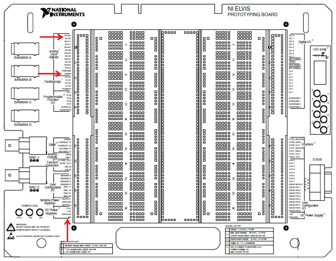
Figure 2: NI ELVIS II series wiring diagram for the Hall effect sensor
The Hall Effect Sensor has three different pins that are numbered below. Pin 1 should be wired to the input voltage (5V or +15V ports), pin 2 should be grounded, and pin 3 should give the output voltage.
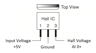
Figure 3: Hall effect sensor wiring diagram
To be able to read the output voltage, wire pin 3 to the positive analog input 0 port [AI 0+] and the negative analog input 0 port [AI 0-] to ground.
Hall Effect Switch
The Hall Effect Switch uses the same ports as the sensor, but requires one extra component. In addition to the connections made for the sensor, a pull up resistor needs to be added between pin 3 and the +5V supply of the switch. A 1 kΩ resistor was used in making this tutorial, but a wide range of resistors will work. A diagram of this new circuit is shown below.
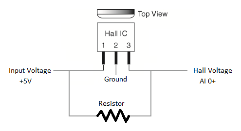
Figure 4: Hall effect switch wiring diagram
Hall Effect Switches experience an important phenomenon called hysteresis. If the distance of a magnet to the switch is plotted against the output of the sensor, the threshold magnetic field strength required to change the output will be different depending on whether the magnet is moving towards or away from the switch.

Figure 5: Effects of hysterisis on Hall effect swtiches
The output will always be LO for field strengths greater than Bmax and HI for field strengths less than Bmin. In the plot above, Bmax would correspond to the magnetic field strength when the magnet was 3/10 of an inch from the sensor and Bmin would correspond to the magnetic field strength when the magnet was 4/10 of an inch away. Again, this could be the other way around depending on the internal circuitry of the switch being used. The difference between Bmax and Bmin is a good measure of the noise immunity of the sensor.
Software Instructions:
Hall Effect Sensor
Open 'Magnetic Field Measurements.vi,' found in the downloads section of this tutorial. This VI is a very simple one that uses the DAQ Assistant express VI to access the analog input 0 port. It also features a waveform chart that displays the Hall Effect voltage reading and a while loop that allows the VI to run and take data continuously. Before running the VI, the DAQ Assistant needs to be linked to the proper channel on the connected device. To do this, open the block diagram, right click on the DAQ Assistant, and select “properties.”
When the properties window (shown below) opens up, right click where “Voltage” is highlighted and select “Change Physical Channel…”
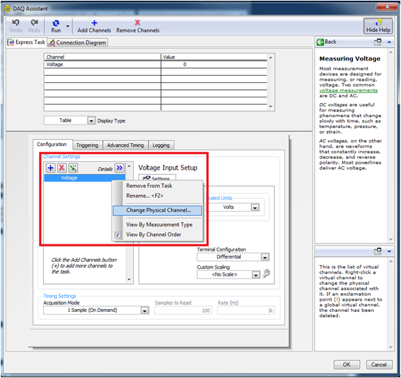
Figure 6: Software configuration for Hall effect sensor
Navigate the menu that pops up to the analog input 0 voltage of the device connected. The device used in the picture below is a myDAQ called Dev5 (device #5) on this computer.
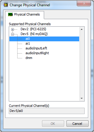
Figure 7: Software configuration for Hall effect sensor
The VI is now ready to detect magnetic fields. Switch the view to the front panel and start the VI. As a magnet is moved closer to the sensor, the signal should either increase or decrease, depending on the direction of the magnetic field. The strength of two different magnets can be compared if they are held at the same distance from the sensor (at different times). The stronger magnet will cause a greater change in the output voltage.
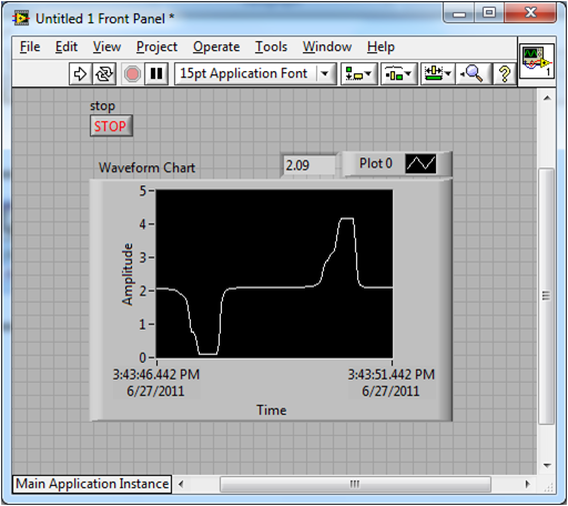
Figure 8: Front panel of 'Magnetic Field Measurements.vi' used with Hall effect sensor
Hall Effect Switch
To get a measurement from your Hall Effect Switch, use the same VI and VI preparation process as with the sensor. As you can see, the output behaves as expected, and jumps immediately from HI to LO and LO to HI.
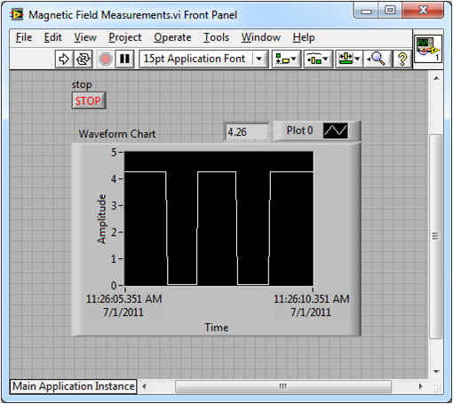
Figure 9: Front panel of 'Magnetic Field Measurements.vi' used with Hall effect switch
Applications Engineering
National Instruments
- Mark as Read
- Mark as New
- Bookmark
- Permalink
- Report to a Moderator
nice work, which sensor are you using? is it allegro A3240?
Or Hirshfeld
https://il.linkedin.com/in/orhirshfeld
Or Hirshfeld
Application Engineer
Certified LabVIEW Developer
SK- Electronika
+972-545844555
Or.Hirshfeld@SK-Advanced.com
il.linkedin.com/in/orhirshfeld
