- Document History
- Subscribe to RSS Feed
- Mark as New
- Mark as Read
- Bookmark
- Subscribe
- Printer Friendly Page
- Report to a Moderator
- Subscribe to RSS Feed
- Mark as New
- Mark as Read
- Bookmark
- Subscribe
- Printer Friendly Page
- Report to a Moderator
Contact Information
University: University of Warwick
Team Members (with year of graduation): Phil Littler (2015), Oliver Redgrove (2015)
Project Supervisor: Extra Curricula project
Email Address: phil.littler@hotmail.co.uk
CAN based Data Acquisition System and Driver Interface for Formula Student Application
Description
The aim of this project was to create a platform for a customisable data acquisition system to serve as the basis for vehicle testing on a Formula Student car.
Products
Hardware
- 3 x myRIO
- 2 x Stratom X-CAN Adapter
- Farringdon SWIS10-R Steering Wheel
Software
- LabVIEW 2014
- Diadem 2014
- Data Dashboard for Android
The Challenge
Having built our most reliable car last year (Figure 1), we aim to continue to improve and are hoping to be one of the top 10 teams in the UK. To achieve this goals, we need to log sensor data from the car to help understand the current vehicle performance and to influence future design decisions. The data also helps in driver training, especially the use real-time feedback.
A bespoke solution was desirable as this provides increased flexibility and room for future expansion. It also allows for better integration with the vehicle, including a custom interface with an existing steering wheel display.
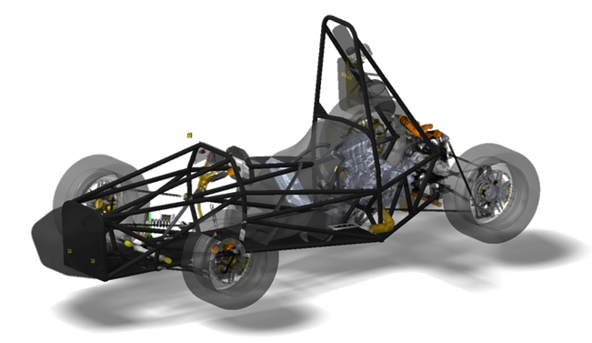 Figure 1: Last year's WR4 vehicle
Solution
To meet the challenge a two node acquisition system that can do multi-rate sampling of both analogue and digital data was created. For practicality the system logs data to a USB flash drive and is interfaced with an existing Farringdon Steering wheel.
To start with we familiarised ourselves with the myRIO platform by logging built in sensor data. This allowed us to quickly create a simple, one device, logger which helped in the development of our electronic shifter. This initial code was not expandable and so a new architecture was conceived with the help of our assigned support engineer.
This architecture included using two nodes; one in the cockpit and one at the rear of the car. This allows for modularity and a reduction in the routing of wires so once installed the front node can record additional sensors without too much difficulty. The layout of the system can be seen in Figure 2.
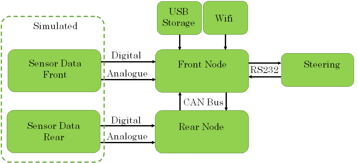
Figure 2: System Overview
Steering Wheel
The team inherited a Farringdon SWIS10-R wheel (Figure 3) which has a number of LED seven-segment displays, a set of shift lights, warning lights and four buttons. After contacting Farringdon, they were kind enough to provide the communication protocol for the wheel. It uses an RS-232 interface at 192kbs baud rate. It receives a 48 byte packet which contains all of the relevant data to drive the displays, and then immediately returns a 4 byte package which contains the data from the buttons. All of the displays can either display the corresponding gauge values or be forced to render characters.
Initially the desired functionality consists of:
- Gear
- Shift lights
- RPM
- Vehicle Speed
- Current Selected Driver
- User selectable gauge
- 4 warning lights
With access to the full protocol however, the steering wheel functionality is fully customisable and the displays can show any combination of characters that can be rendered using seven-segment displays.
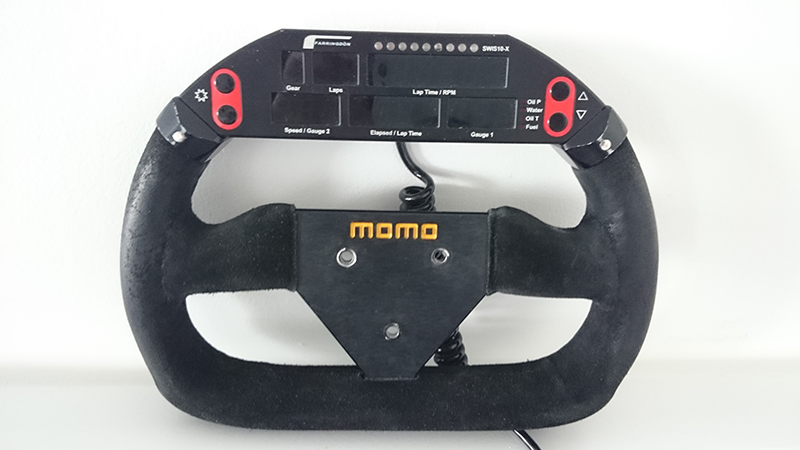
Figure 3: Farringdon SWIS10-R Steering Wheel Display
Rear Sensors
The sensor signals connected to the node at the rear section of the car consist of:
- Digital pulse train from rear wheel speed and RPM sensors
- Analogue TPS (Throttle Position Sensor) values
- Analogue Engine Temperature
- Analogue Shifter Position
- Any additional analogue channels for specific tests
Front Sensors
The sensor signals connected to the node at the front section of the car consist of:
- Digital pulse train from front wheel speed sensors
- Analogue position sensors from pedal box (Accelerator and brake)
- Analogue pressure sensors for brakes
- Accelerometer data
- Gyro data
- Any additional analogue channels for specific tests
Sensor Simulator
During the development of the data acquisition system, a myRIO was used to imitate signals coming from the vehicle. The VI initially reads in values from a TDMS file placed in the root directory on the myRIO and creates four waveforms from the Time, Accelerator Pedal Position (APP), RPM, and Wheel Speed channels within the TDMS file.
It then enters the stream state, looping at the same rate as the TDMS sample rate. The loop index is used to determine the data sample to be used from each waveform. In order to produce the pulse train data a simple 50% duty cycle square waves is generated using the FPGA using a time period set by the real-time VI.
Rear Node
FPGA
A custom FPGA personality was used to determine the time period of the digital pulse trains. A timed loop cycles at the 40 MHz clock rate and checks for a rising edge. If no rising edge is detected then a shift register value is incremented by one (Figure 4). Once a rising edge is detected, the value is checked to ensure it within the expected range and if it is, it is entered into the appropriate ele
ment of a 5 element ring-buffer.
Figure 4: Frequency counter in custom FPGA profile
RT Producer Loop
The Real-Time application uses a producer-consumer architecture to ensure no data samples are lost. The producer consists of a timed loop with a unique case for each channel being sampled as shown in Figure 5 These are called sequentially based on the loop index. It was desirable to allow the sample rate of each channel to be set individually, so to achieve this, a second case structure is used which determines if a sample should be taken based on the loop time, number of channels and sample rate. This structure allows new channels to be easily added by duplicating cases.
When taking a sample, the value is read in from the FPGA, adjusted to the appropriate units and set as the payload for a CAN frame. The timestamp is taken from the current time and the ID is unique for each channel in the entire system. The complete CAN frame is then placed on the queue.
The gear position is also sampled in the same way, although the payload is instead a function of the previously sampled wheel speed and RPM rather than being taken directly from the FPGA as the vehicle has no dedicated gear position sensor.
Figure 5: Rear node producer loop allowing for multi-rate acquisition
RT Consumer Loop
The consumer loop is a While loop with a state machine architecture. It first initialises a new X-CAN session and then switches to the “Send” state. This state simply repeatedly de-queues elements and sends them on the CAN bus as depicted in Figure 6. If an error is thrown, such as the CAN buffer being full for example, then the state changes to clear the CAN session and re-initialise to try to clear the error without the need for external interaction.
Figure 6: Rear node consumer loop sends CAN frames
Front Node
FPGA
The front node shares the same custom FPGA personality as the rear node in order to sample the front wheel speed sensors.
RT Producer loop
Again, a producer consumer architecture is employed to capture all samples. The same basic structure as the rear node is used with states for each channel and CAN frames being sent to the queue. Additionally, the CAN bus is sampled at a fixed rate (matched to the send rate) in order to read the data from the rear node. The sampled CAN frames are also placed straight onto the queue. All received CAN frames are also read in this loop and depending on the ID, the appropriate case is called and the data sent to the corresponding shared variable. This allows all data channels to be read wirelessly over WiFi using Data Dashboard. These variables are also used for the driver interface as missed samples are not critical for this application.
RT Consumer Loop
The consumer loop is a While loop with a state machine architecture. The initialisation state reads the current number of TDMS files on the USB flash drive so as not to override any previous sessions. It also initialises a number of other variable values (primarily for testing purposes currently) and calls the “Dormant” state. This state continuously de-queues elements and waits for the appropriate input from the steering wheel to begin logging. Once it receives this input, it enters the “Open File” state which opens a new TDMS file with the current Date and file number. It also sets the driver information based on the driver number set on the steering wheel and calls the “Logging” state. This state de-queues each element and determines the correct channel based on the frame ID, with a case for each channel. Each channel is then saved as a separate group in the TDMS file with a “Data” channel based on the payload and a “Time” channel based on the timestamp as shown in Figure 7. This structure was thought to be the most convenient and flexible to allow for variable sample rates. When the user stops logging, the “Flush” state is called which saves any remaining queue elements in the same way until the queue is empty, and calls the “Close File” state which simply closes the file and re-enters the “Dormant” state.
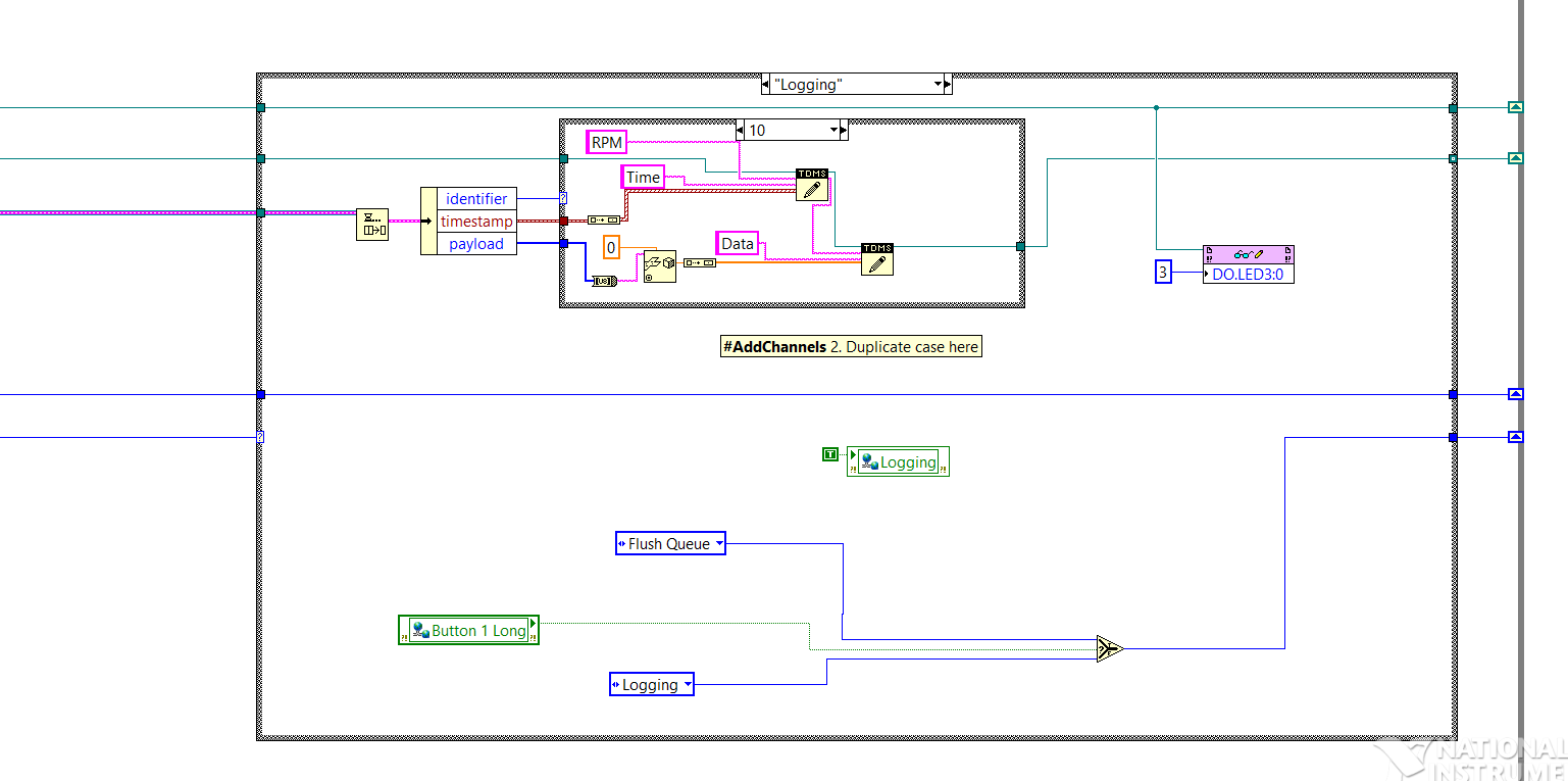
Figure 7: Logging state of consumer loop on front node
RT UART Loop (Wheel Communication)
A third loop is used to communicate with the steering wheel. A UART session is initialised using the NI VISA blocks. It then continuously loops through the “Send – Read – Dormant” states. A sub-VI generates the appropriate data packet to be sent to the wheel, with many of the inputs being taken from the shared variables written by the producer loop. After reading back the 4 byte packet from the wheel, the first byte is taken and split into its individual bits which correspond to the button inputs.
Two shift registers are used to hold the currently selected driver and user-configurable gauge. These increment based on a rising edge from the appropriate button input.
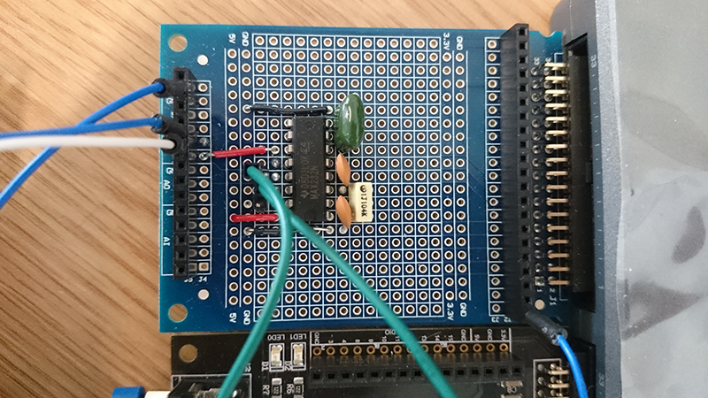
The UART output on the myRIO outputs 3.3v logic outputs, which are not directly compatible with the RS-232 standard used by the wheel. A small circuit was built on prototyping board using a MAX232 IC which shifts the voltage to the correct levels as shown in Figure 8.
Figure 8: MAX232 based RS-232 level shifter circuit
Conclusion
A demonstration of the final system can be seen in the video below. Clearly it is still in the early stages of development as a much more robust solution is required before being fitted to the car. Most of the required functionality is present however, and this makes for a good base on which to expand.
Why NI?
Without the support of National Instruments, it is unlikely that a system with such a range of functionality could have been completed in such a short space of time. The project was entirely extra curricula and the majority of the code was developed from scratch in a matter of weeks without much previous experience of LabVIEW. This was partly due to the accessibility of the myRIO platform which allows functionality to be quickly built using the express VIs, but then also facilitates more advanced features once the user is more comfortable. The multitude of examples available also made learning LabVIEW a painless experience.
Future Recommendations
The current focus is now ruggedising the system for installation on the vehicle and making all of the appropriate connector interfaces and enclosures. If time allows before the FSUK and FSG competitions, the system may be transferred from the myRIO platform to a more robust single-board RIO system.
Additional functionality that could be added for this year’s competition include adding lap timing functionality to the system using an infra-red beacon and interfacing the rear node with the electronic shifter system.
Next year’s team are eager to expand on this project and will hopefully progress towards implementing and integrating more of the vehicle control functionality through the system.
It would also be interesting to further develop the vehicle simulator, perhaps using a cDAQ or cRIO. Data logged to TDMS from this year’s competition could be output from the vehicle simulator and system response could be analysed and fine-tuned based on the exact driver input recorded.
