Using RTL-SDR with Labview, Chapter 1: Labview on Windows
- Subscribe to RSS Feed
- Mark as New
- Mark as Read
- Bookmark
- Subscribe
- Printer Friendly Page
- Report to a Moderator
Code and Documents
Attachment
Overview
Some time ago it was discovered by Antti Palosaari, Eric Fry, and Osmocom that DVB-T TV Tuner dongles using the RTL2832U chipset have a special mode which allows direct access to the I/Q data stream, meaning that a cheap, $20.00 DVB-T tuner can be used as a wideband software defined radio receiver. Please note that this is only a receiver. There is absolutely no transmission capability whatsoever.
There are many software defined radios on the market, from Airspy ($199.00), SDRPlay ($149.00), all the way up professional grade devices from National Instruments, such as the USRP series, which starts around $1000.00 and go all the way up to $9000.00 for a high end device with an FPGA embedded for signal analysis. Most of these SDRs can transmit in addition reception.
The table below shows a comparison between an NI USRP 2954R and an RTL-SDR. Here the limitations of the RTL-SDR become apparent, which is why the RTL-SDR stands in absolutely no competition whatsoever with these devices.
|
USRP-2954R |
RTL-SDR |
|
|
Frequency Range |
10 MHz to 6 GHz |
50 MHz to 1800 MHz (model specific) |
|
Bandwith |
160 MHz (max) |
2 MHz (max) |
|
ADC Bit Depth |
16-bit |
8-bit |
|
2x2 MIMO |
Yes |
No |
|
Transmit |
Yes |
No |
|
Bus |
PCIe x4 |
USB 2.0 |
|
FPGA DSP |
Yes |
No |
Given all these limitations, it is still possible to use the RTL-SDR for many educational projects. After all, the engineer must constantly educate himself to stay current and cannot rely that the knowledge gained in a post-secondary institution will suffice for his entire career.
For more information on projects and software already available, please visit http://www.rtl-sdr.com
Additionally, please note that there is a similar project called SDRLab by András Retzler. Mr. Retzler also uses an RTL-SDR and Labview, but relies on an additional program called rtl_tcp which acquires the signal and transmits the raw IQ data over a tcp connection.
Description
In order to get RTL-SDR to work with Labview, it was necessary to write a wrapper around the rtlsdr.dll, which was written by Steve Markgraf and Dimitri Stolnikov, who, fortunately for us, have made this library available under the GPL. This means we not only have access to the binary .dll release, but also to the documented header file, which gives us all the information we need to call the functions contained therein.
Fortunately, all the heavy lifting of writing the wrapper, packaging it into a vipm package, and documenting its functions has already been done by the author of this paper.
Steps to Implement or Execute Code
Preparing to work with Labview and RTL-SDR
In order to begin working with RTL-SDR under Labview, a little bit of preparation is needed. First, an RTL-SDR must be purchased. These devices are readily available on various sizes, including amazon.com and ebay. Searching for “rtl-sdr” will yield many results.
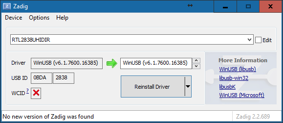
When a RTL-SDR device is available, it must be connected via USB to the computer. Windows will then proceed to install the drivers. The drivers installed by the operating system itself are for the DVB-T function. New drivers must be installed which are supported by the libusb interface that the rtlsdr.dll uses to interface with the hardware. To do this, download a tool called Zadig, available at http://zadig.akeo.ie/ . Once downloaded you can select the RTL-SDR device and install the WinUSB drivers.
Once the WinUSB drivers have been installed, the computer and the operating system are ready. What you can do at this point to verify that the device is working as it should is to download sdrsharp. It is a C# based SDR software which allows using the RTL-SDR as well. It is available from www.airspy.com in the downloads section under core tools. It is part of the SDR Software Package download.
Using RTL-SDR with Labview
In order to get RTL-SDR to work with Labview, it was necessary to write a wrapper around the rtlsdr.dll, which was written by Steve Markgraf and Dimitri Stolnikov, who, fortunately for us, have made this library available under the GPL. This means we not only have access to the binary .dll release, but also to the documented header file, which gives us all the information we need to call the functions contained therein.
Fortunately, all the heavy lifting of writing the wrapper, packaging it into a vipm package, and documenting its functions has already been done by the author of this paper. Consequently, all the user has to do is install the library and use the functions, just like with any other hardware. All the .dll ugliness has already been hidden. Unfortunately, the author does not have acccess to the pro version of the VI Package Manager, so it is not possible to download this package from a repository.
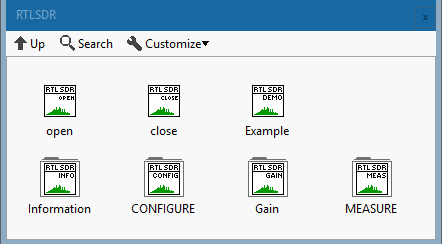
Upon installation of the library, which is conveniently packaged in a vi package manager file, there will be a new palette in the block diagram.

In this palette, all the functions required to work with rtl sdr have been combined for easy access.
The Example VI contains an example which opens a device, retrieves anumber of samples, computes and FFT, then displays the results.
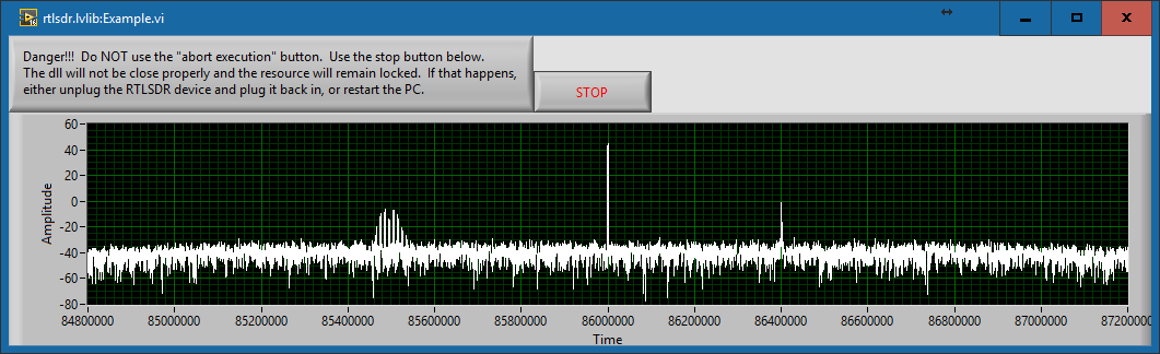
This example shows one real signal. At 85.5 MHz, there is a two tone, FM modulated signal generated by using a signal generator, and a second signal, at 86.4 MHz, which is the third harmonic of the local oscillator. The local oscillator of the RTL-SDR operates at 28.8 MHz. It leaks into the signal and since the board was not designed to limit oscillator leakage, it can be seen at multiples of 28.8 MHz. Fortunately, the higher the tuned frequency, the lower the power level of the oscillator harmonic. Theoretically, we could mask these frequencies in the DSP chain, but it is important to know that they are there.
We can also see another limitation of cheap SDRs. This is called the DC spike, and happens because there is always a small DC offset in the downconverter and will always be in the center, no matter what center frequency the device is tuned to and will always be at the center frequency. There are several software techniques used in other software packages, such as SDR#, to correct this. These applications correct the display only, however, using estimation techniques. The basic problem remains.
An additional reason for the DC spike is that the rtlsdr .dll returns samples as an array of U8. This means that there are no negative values and that the signal amplitude is centered at about 127, which is the midpoint between 0 and 255. To fix this, simply convert to a signed data type (double is good for additional signal processing) and subtract 127.5 from the array. This will remove the offset and recenter the signal around 0.
I'm going out on a limb here and speculate that the ADCs on the rtl-sdr have a positive range, much like the ADCs on an Arduino have a range of 0V to 5V. To acquire an audio or RF signal (which usually bob around 0V) with ADCs like this, a dc bias is applied, centering the signal around VADCmax/2 (in the arduino example, this would be 2.5V). Then it's acquired and processed.
Technical Details
The entire library is based upon calls to a shared library, or dll file on a windows system. In order to use shared libraries from a labview program, it is necessary to use the “Call Library Function” function from the “Libraries and Executables” sub-palette, which is under the “Connectivity” category. A simple example of a call to this library looks like this:
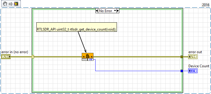
Double clicking on the node brings up the configuration screen.
The function tab defines where the library is, which function to call, and how to perform the function call.

The real work however goes into the parameters tab. Here we defined all the parameters of the function call, and this the connectors on the “call library function” connector pane.
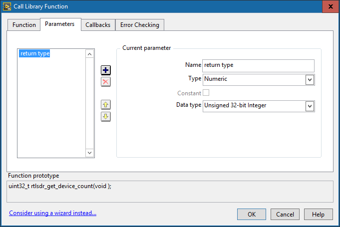
This is only a very simple example for a function which only has a numeric return. The reader will appretiate that this can get quite complex if pointers to arrays and complex data types are used in function calls. Please refer to the attached code for more detailed examples, and also to the Labview Help.
Outlook
This was the first part in a series on RTL-SDR. The second part will focus on using a MyRIO and attaching the RTLSDR directly to it. At this point, the data is gathered by the Labview RT system. Streaming directly into a cRIO/myRIO system means that we no longer have to bother the host with acquisition, and can then use the integrated FPGA as an FFT/DSP coprocessor to Labview RT.
The key learing of that part will be compiling the rtlsdr shared library directly on a myRIO, as there is currently no binary package available. Don’t worry, it sounds uglier than it is.
Sources
http://www.kerrywong.com/2014/11/16/testing-an-rtl-sdr-spectrum-analyzer/
Requirements
Software
Labview 2016
Hardware
RTL-SDR Dongle
Notes
I have tried to make this library bug free and consistent with the style guides publised by National Instruments. Should find any bugs, or have any improvement ideas, please feel free to comment or send me a pn.
Disclaimer
This is a private contribution to the community and is not endorsed by rtl-sdr.com, National Instruments, or any other entity, except me. Additionally, as this is example code, I will give no warranty for anything.
Example code from the Example Code Exchange in the NI Community is licensed with the MIT license.
- Mark as Read
- Mark as New
- Bookmark
- Permalink
- Report to a Moderator
This looks absolutely great!
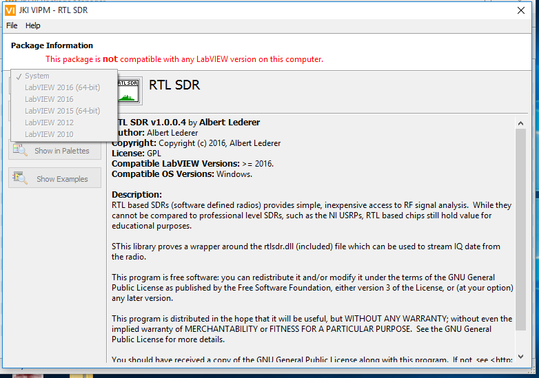
Maybe it is a problem on my end, but I can't seem to install it. VIPM tells me there are no supported versions of LabVIEW installed.
NI Technical Support Engineer
- Mark as Read
- Mark as New
- Bookmark
- Permalink
- Report to a Moderator
I have the same issue on my end as well
- Mark as Read
- Mark as New
- Bookmark
- Permalink
- Report to a Moderator
It appears that the files were created using LabVIEW 2016 . Would it be possible to save this an older version, like version 15.0 (the highest I have access to)? Possibly the oldest version that still fully supports your implementation?
- Mark as Read
- Mark as New
- Bookmark
- Permalink
- Report to a Moderator
Gentlemen,
Yes, the wrapper was written in LV2016, 32-bit.
I apoligize for the late reply. It wasn't due to laziness, but I was out of the country with no internet access...
Since there seem to be some version conflicts and issues with previous Labview Versions, I've also uploaded the code saved for LV2015 as a zip file. Just open the lvlib in the folder and all the vi's are there. Please be aware that depending on where you unzip the files, you will have to alter the path to rtlsdr.dll in the call library function node. This is imporatant. Otherwise the vi's will not find the rtlsdr library and cause errors.
I hope this helps...
- Mark as Read
- Mark as New
- Bookmark
- Permalink
- Report to a Moderator
Which version ob LV is installed on your system? I've done all this in LV2016, 32-bit... I hope it's just that and not that I messed up in creating the vipm package...
- Mark as Read
- Mark as New
- Bookmark
- Permalink
- Report to a Moderator
Most likely this is a version problem with VIPM, and not LabVIEW.
VI packages built in VIPM 2014 or later, as this VIP is, can only be installed using VIPM 2014 or later. If you try to use one of these packages in VIPM 2013 or earlier, you get the error message you see (which admittedly is not a good description of the actual problem).
If you receive this error, you should install VIPM 2014 or 2016, and try again. If you have a Pro license of VIPM 2013 or earlier, it will not automatically give you a Pro license for 2014, and you will need to decide how to proceed.
Christian L, CLA
Systems Engineering Manager - Automotive and Transportation
NI - Austin, TX
- Mark as Read
- Mark as New
- Bookmark
- Permalink
- Report to a Moderator
Hi,
the Package was created using VIPM 2014 and I haven't got the pro version. So that could indeed be the problem...
- Mark as Read
- Mark as New
- Bookmark
- Permalink
- Report to a Moderator
Albert, you do not need the Pro version to create the VIP properly, and you having the Pro version would not make a difference in this situation.
My comment about the Pro version is directed at anyone interested in using your VIP, that may consider upgrading from VIPM 2013. When you upgrade from VIPM 2013 Pro, you do not automatically receive the Pro version of VIPM 2014. You need to get a new activation code from JKI, by paying the upgrade license cost.
Christian L, CLA
Systems Engineering Manager - Automotive and Transportation
NI - Austin, TX
- Mark as Read
- Mark as New
- Bookmark
- Permalink
- Report to a Moderator
Ah, ok, then I understood the post wrong. Sorry.
- Mark as Read
- Mark as New
- Bookmark
- Permalink
- Report to a Moderator
Hello Albert!
Recently acquired Hackrf one in China, downloaded the library and did everything step by step as described above, but Labview does not see the device. SDR radio works fine. As I am a beginner in Labview, I can not understand why? After reading the comments I saw that someone had a similar problem. Maybe you can help me to understand how to fix the error. Thanks in advance
- Mark as Read
- Mark as New
- Bookmark
- Permalink
- Report to a Moderator
Hi,
the library only works with devices using the RTL2832U chipset. The HackRF is based on a different chipset, and therefore requires a different library and is therefore not supported by this project.
Check this link for supported radios: http://www.rtl-sdr.com/about-rtl-sdr/
However, implementing the HackRF One support should not be that difficult. Basically, one would need to write a wrapper around the .dll to make it ready to use. Since it's open source, you do have access to all the header files, and therefore all the entry points of the .dll. This isn't a very complex task, it's just a lot of work.
- Mark as Read
- Mark as New
- Bookmark
- Permalink
- Report to a Moderator
Thank you Albert for your answer. Today I'll see what my chipset and just write. Actually I want to use two hackrf to build FMCW radar for unmanned boats in which the main code works in labview. At the moment I suspect that I bought the wrong chipset and therefore will program it into gnuradio as the transmitter, the second hackrf buy with the right chipset and everything should work. Do you think Albert? If you have any thoughts please let me know.
Thank you again!
Andrew
- Mark as Read
- Mark as New
- Bookmark
- Permalink
- Report to a Moderator
Hi,
I'm not sure that HackRF is the proper tool to use to build an FMCW radar. Theoretically this could be done a lot cheaper. Since radars seem to be all the rage now, I've got a couple of links:
DEFCON 19: Build your own Synthetic Aperture Radar
(I've actually built this using a MyRIO and 2 x 2.4GHz WIFI Antennas. Works really well, and you don't actually need a radio)
MIT Courseware that the above video is based on...
Build a Small Radar System Capable of Sensing Range, Doppler, and Synthetic Aperture Radar Imaging
Hope this helps.
- Mark as Read
- Mark as New
- Bookmark
- Permalink
- Report to a Moderator
Hello Mr.Lederer,
I hope you are doing fine.
I am trying to interface RTL-SDR with Labview and am planning to make a simple "FM Receiver project" out of it.
I went through quite a few articles about the same and in turn have downloaded the "RTL-SDR" module suggested through the link in the trailer mails. But sadly, I could see that the module only consists of an example ( https://decibel.ni.com/content/docs/DOC-48590 ) and am not able to deduce much out of it.
All I observe is that the example does not work when I unplug the dongle, but I could still not clearly see if the observed waveform is actually because of the antenna deducing from the surrounding.
My doubts are as follows:
- Could you please let me know how I can take an input from RTL- SDR as I could see that the NI-DAQ doesnt work for rtl-sdr?
- In the example mentioned, Is there a way to check the frequency of waveform?
- Does the waveform obtained in the example actually represent the EM-Wave detected?
I am so sorry if my doubts seem silly but I am really stuck here and any help here would be greatly appreciated.
Vijay
- Mark as Read
- Mark as New
- Bookmark
- Permalink
- Report to a Moderator
Hi,
um. the example does work. I used it just a minute ago to verify that it does work. I generated an FM modulated signal using an Rohde & Schwarz SML01 signal generator and was able to pick up the signal very well. If you note, the signal acquired in the example above
The first thing I would do is verify that the rtl-sdr dongle works properly. For this, download sdr# and verify that the dongle works. If this works, the example works too. Also, please don't unplug the dongle. If you do, it won't work...
To read an input signal, simply use the read vi. It will return a number of IQ samples and you can use those to demodulate the signal. Simply put the read vi in a loop to continuously read signal. If you check the example, I compute an FFT. You can use this to get frequency information you want.
To your last point, the output isn't really a waveform. It's an array of IQ samples, organized like this IQIQIQIQIQIQIQIQ....IQ
In case you're not familiar with IQ samples check this link:
http://whiteboard.ping.se/SDR/IQ
It's a good introduction...
- Mark as Read
- Mark as New
- Bookmark
- Permalink
- Report to a Moderator
Hi all,
I don't know if it has already been noticed, but the DC spike is easily removed by subtracting 126 to the IQ raw data in complex form. It happens that the 8 bits IQ data stream out of the RTL is centered around 128 (2^7).
I implemented this simple subtraction and the center frequency spike is completely gone.
Regards,
Francesco.
- Mark as Read
- Mark as New
- Bookmark
- Permalink
- Report to a Moderator
Hi IZ2DQB,
yeah, I did notice this after I had writte the post. Good spot though. I will update the article accordingly...
Just for documentations sake: be careful when you do this though, and change the data type to something bigger. The U8 samples go from 0 to 255, and if you just subtract 127 from this, you'll cut of the lower half. In the FM demodulator, I subtract 127.5 after converting to float. Link is here. The FPGA implementation does something similar, just with fixed point arithmetic.
What you can also do if you're staying on windows, just to make sure all DC is gone, is use the AC & DC estimator vi over an array of data points, and then subtract that. The dynamic character of this will also get rid of any dc offset not purely caused the by U8 problem...
- Mark as Read
- Mark as New
- Bookmark
- Permalink
- Report to a Moderator
- Mark as Read
- Mark as New
- Bookmark
- Permalink
- Report to a Moderator
Albert good morning, I'm using the example that comes in the files to feel the spectrum but I have some doubts. For example I transmit with a USRP 2920 in the frequency of 910MHz and I execute the example of RTL but in the graph of the spectrum I do not observe that signal.
- Mark as Read
- Mark as New
- Bookmark
- Permalink
- Report to a Moderator
Hi Marefrei,
from your front panel, I can see that you are using a sample rate of 10MS. This does not work, as the device only supports sample rates of up to 3.2MS, and then you can expect dropped packets. Set your sample rate to 2.4MS and it should work as expected. That's what "bandwidth" means in the post. If you are looking for something with higher bandwith, then an rtl-sdr device is definitely not right for you. You can try an airspy or something like that, but as far as I know, there is no labview interface for that.
Additionally, if you have further problems, please attach the block diagram as well, or better yet, the entire .vi It's kinda difficult to see all the parameters you've entered just from the front panel.
Br,
Albert
- Mark as Read
- Mark as New
- Bookmark
- Permalink
- Report to a Moderator
Hi Albert,
Thanks for your tutorial. I have airspy R2 and i am use labview 2017. I has try the airspy using SDR# and working; and then I put the Example VI and run it, but no device is detected
Its any step what i miss? many thanks
Best regards,
Jimmy
- Mark as Read
- Mark as New
- Bookmark
- Permalink
- Report to a Moderator
Hi Jimmy,
the airspy does not use a RTL2832U-based chipset, and as such is not supported. There was a previous question like this about the hack-rf.
Check this link for supported radios: http://www.rtl-sdr.com/about-rtl-sdr/
Hence the name rtl-sdr... SDR# includes interfaces for many sdr devices, including the rtl-sdr, airspy, hack-rf, and a plethora of others. If you check out the sdr# source code here, you can see that sdr# implements software modules for each of the sdrs it supports. You can think of this library as the specific part that provides the rtl-sdr interface.
The solution would be to write an abstraction layer for these sdrs, providing a uniform interface for receiving data. Unfortunately, I only have access to an rtl-sdr, so I have no way of developing those interfaces.
- Mark as Read
- Mark as New
- Bookmark
- Permalink
- Report to a Moderator
Can someone add this to the 'NI LabVIEW Tools Network' Repository?
@Albert: really great work - I just came along and it worked almost instantly! For some reasons the links to the rtlsdr.dll were not adjusted automatically when installing the package. Is there a way to do that with the packet installer functionality?
- Mark as Read
- Mark as New
- Bookmark
- Permalink
- Report to a Moderator
Hi,
I'm going to check the requirements to see if it's possible for me to add this to the labview tools network. I'm not familiar wit the process, but I will check into it. What exactly was the problem you are having? You installed the .vipm package and it didn't update the path to the rtl-sdr library?
- Mark as Read
- Mark as New
- Bookmark
- Permalink
- Report to a Moderator
That exactly was the problem.
- Mark as Read
- Mark as New
- Bookmark
- Permalink
- Report to a Moderator
Hello! Can you help me with the labview chart for the 2832u receiver? Thank you!
- Mark as Read
- Mark as New
- Bookmark
- Permalink
- Report to a Moderator
Very cool program. I have worked with RTL-SDR with SDR# and SDRConsole for many years but I am new to Lab-view. I look forward to exploring this. Is there a 64-bit version of this? This works OK on my student edition of 2017 32-bit but my 2018 64-bit edition gives me an error about it not being 64-bit. thanks in advance!
- Mark as Read
- Mark as New
- Bookmark
- Permalink
- Report to a Moderator
I want to thank you for the work you did on the RTL-SDR.
Have you looked into anything with the KerberosSDR? I was able to use some of your code to see all 4 receivers, but that is where I stopped. I have read that the GPIO pins turn on the noise source for calibrating the 4 radios.
Any ideas?
Thanks.
- Mark as Read
- Mark as New
- Bookmark
- Permalink
- Report to a Moderator
Hello,
Thank you for providing this code. You mentioned that you were going to work on LabVIEW RT version. Have you had chance to develop that version?
G Systems, www.gsystems.com
Certified LabVIEW Architect
Certified LabVIEW Embedded Systems Developer
Certified Professional Instructor
- Mark as Read
- Mark as New
- Bookmark
- Permalink
- Report to a Moderator
Hi. Sorry for the wait...
Ok, so, 64-bit isn't going to work. The .dll provided by osmocom is 32-bit and you can't mix bitness in the same application. I.e. you can't call a 32-bit dll from a 64-bit application. I don't know if there is a 64-bit version available. I haven't found one...
Number 2: KerberosSDR sounds interesting, but I haven't got one so I can't play with it. I think what you need to do is use 4 separate device ids for the initialisation of each SDR. I do have 2 RTL-SDRs now, so if I get time this weekend I will try to get the two to work...
Number 3: Labview Realtime. The implementation exists an is documented in chapter 2. https://forums.ni.com/t5/Example-Code/Using-RTL-SDR-with-Labview-Chapter-2-Labview-RT/ta-p/3538912?p...
- Mark as Read
- Mark as New
- Bookmark
- Permalink
- Report to a Moderator
Hello
Sir hope you will be having a productive day.
Kindly guide me for what purpose is the second download file with your respected name.And where should we place (location) of this file.
First one download is for the VIs+dll file obviously.
- Mark as Read
- Mark as New
- Bookmark
- Permalink
- Report to a Moderator
Hi,
The example is just so awesome. I seem to get signals from my RTL-SDR V3. Could someone help me to pick the waveform up and use a small portion of it, demodulate that to an audible WFM audio signal and send this out to the speaker attached to the sound card? For example to listen to an FM radio station? What are the steps I need to do, to be able to listen to a radio station using this wonderful RTL-SDR library?
- Mark as Read
- Mark as New
- Bookmark
- Permalink
- Report to a Moderator
I wrote an example for this a while back. Check it out:
Using RTL-SDR with Labview, Appendix A: Simple FM Demodulator - NI Community
