- Subscribe to RSS Feed
- Mark Topic as New
- Mark Topic as Read
- Float this Topic for Current User
- Bookmark
- Subscribe
- Mute
- Printer Friendly Page
Adjusting color and brightness of 2.8" TFT LCD color touch screen - SOLVED!
05-18-2012 08:09 AM
- Mark as New
- Bookmark
- Subscribe
- Mute
- Subscribe to RSS Feed
- Permalink
- Report to a Moderator
Hi all,
I just ordered a 2.8" TFT Color LCD,touch screen shield V1.2 for Arduino 168/328 together with the Arduino Uno Microcontroller Board ATMEGA328, USB to set up a light source that provides white, blue, green or red light (complete screen) for a defined time and with defined brightness. After installing the required software (LabView is already installed) I went through the provided Arduino examples to find code for my application but unfortunately I did not find a VI that seems suitable for my application.
This is an example-sequence of commands I would like to execute:
1. Switch on display and set color (all pixels) to white at defined brightness
2. Change color to red at defined brightness
3. Dimm brightness to zero in ten iterations (or just turn off light)
... Repeat steps 2. & 3. with different colors and varying duration of illumination
I would like to implement this work flow into an existing VI infrastructure that controls a camera. The next step would be to do the same but with selected pixels of the display (such as a ROI). Does anyone have a suggestion on how to realize that? I would very much appreciate your assistance.
Thank you very much & have a nice weekend!
05-18-2012 04:34 PM
- Mark as New
- Bookmark
- Subscribe
- Mute
- Subscribe to RSS Feed
- Permalink
- Report to a Moderator
Hi there.
I would hazard a guess that the LCD vi examples are for charcter based LCD modules in which case you will need to desing your ow vi driver and also modify the LVIFA_Base.ino sketch
to include custom code to drive your LCD.
Also, putting Labview aside for the moment, have you tried just using the Arduino and its IDE to achieve what you want?
Regards,
Dale
05-19-2012 07:08 AM
- Mark as New
- Bookmark
- Subscribe
- Mute
- Subscribe to RSS Feed
- Permalink
- Report to a Moderator
Hi Dale,
Thank you for your comment! I am still waiting for the hardware - as soon as I have received it (next week) I will dig deep into the task and try to find a good solution. Other websites show LabView-independent example codes and methods for setting values of defined pixels. One way would be to create specific images, save them on an SD card and load the images from the card. But this is quite complicated and supposably not automation-friendly. A LabView-based way would be much more comfortable. Any help still very much appreciated!
Best regards,
Daniel
06-02-2012 03:04 AM
- Mark as New
- Bookmark
- Subscribe
- Mute
- Subscribe to RSS Feed
- Permalink
- Report to a Moderator
Hi there,
The display has arrvived and I can actually control it using the Arduino IDE and (a truncated version of) the TFT_lib that is provided by Nuelectronics. Here is my very first very simple code:
#include <TFT_Graphics.h>
Graphics tft;
void setup()
{
tft.initialize(LCD_HORIZONTAL);
tft.ClearScreen(WHITE);
//tft.FastSolidRect(85, 10, 240, 231, BLACK);
//tft.DrawCircle(160,120, 100, BLUE, 1);
}
void loop()
{
tft.ClearScreen(BLACK);
tft.FastSolidRect(85, 10, 240, 231, BLUE);
delay(1000);
tft.ClearScreen(BLUE);
tft.FastSolidRect(85, 10, 240, 231, BLACK);
delay(1000);
}
The following images show what my loop is doing:
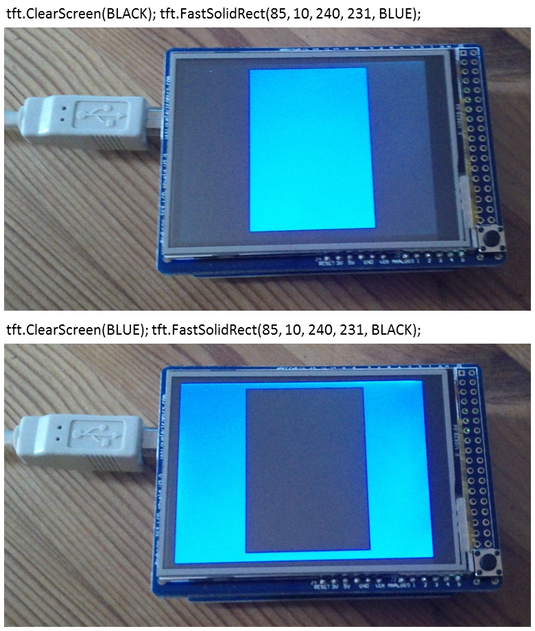
Unfortunatly I did not find commands for adjusting intensity or backlight. I assume this is not possible.
I tried other libraries such as Henning Karlsen's UTFT library and variety of alternatives but nothing else, aside the TFT_lib, worked... Any idea how to get the UTFT (or any other) library running for my hardware configuration?
Anyway, my simple code works fine and is good enough for a start - no need for adjusting intensity or backlight. In the next step I would (somehow) like to merge this code with LIFA and send commands such as ClearScreen(BLUE) to the board for controlling the LCD using LabView. Any ideas how to proceed from here?
Thank you very much!
06-02-2012 10:10 PM
- Mark as New
- Bookmark
- Subscribe
- Mute
- Subscribe to RSS Feed
- Permalink
- Report to a Moderator
So assuming you have downloaded the labview support package for Arduino, you will need to modify the
LabVIEWInterface.ino file by adding a new Case statement and function.
See my code https://github.com/daleMelbourne/LVIFA_Base
If you look in the file LabVIEWInterface.ino, you will see I have added
/*********************************************************************************
** ISM-RLY
*********************************************************************************/
case 0x40: // Toggle Relay
SPI.begin();
SPI.setDataMode(SPI_MODE0); //SPI Mode 0
pinMode (command[2], OUTPUT);
digitalWrite(command[2],HIGH);
//SPI.setClockDivider(SPI_CLOCK_DIV64); // 16MHZ/4 = 4MHZ
retVal = setIsmRly(command[2],command[3],0); // Relay card CS, relay to toggle, R/W
Serial.write( (retVal >> 8));
Serial.write( (retVal & 0xFF));
// Serial.write('0');
break;
This calls my custom function
int setIsmRly(int rlyCard, int rlyPosition, int readWrite)
{
const int slaveSelectPin = rlyCard;
int rlyRetVal=0;
//if(rlyPosition > 0){
digitalWrite(slaveSelectPin,LOW);
SPI.transfer(0x46);//Send opcode
delay(50);
SPI.transfer(rlyPosition);
delay(50);
SPI.transfer(readWrite);
// rlyRetVal = SPI.transfer(0xFF);
digitalWrite(slaveSelectPin,HIGH);
return rlyRetVal;
//}
}
So you will need to take an existing .vi example for the arduino and modify it to send hex 0x40 (in this case) to call the above function
Dale
06-03-2012 09:07 AM
- Mark as New
- Bookmark
- Subscribe
- Mute
- Subscribe to RSS Feed
- Permalink
- Report to a Moderator
Hi Dale,
Thank you very much for the response!
I copied the extracted files (zip from your page) into a subdirectory (called LV_Base_01) of the LabView 'Firmware' folder and opened the LabVIEWInterface.ino with the Arduino IDE. The Arduino IDE stated that it has to be within a folder called 'LabViewInterface'. Upon clicking OK, a new LabViewInterface sub-folder was created and the LabVIEWInterface.ino file was moved there. Same for the LVIFA_Base.ino which was moved into a folder called LVIFA_Base. Is this normal? In the next step I opened the LabVIEWInterface.ino file and clicked the verify button in the Arduino software - just like that. I received a number of errors for the LabVIEWInterface.ino:
LabVIEWInterface:63: error: expected constructor, destructor, or type conversion before '*' token
LabVIEWInterface.cpp: In function 'int checkForCommand()':
LabVIEWInterface:84: error: 'COMMANDLENGTH' was not declared in this scope
LabVIEWInterface:90: error: 'currentCommand' was not declared in this scope
LabVIEWInterface:92: error: 'currentCommand' was not declared in this scope
LabVIEWInterface:92: error: 'processCommand' was not declared in this scope
LabVIEWInterface.cpp: In function 'void processCommand(unsigned char*)':
LabVIEWInterface:105: error: 'checksum_Test' was not declared in this scope
LabVIEWInterface:132: error: 'writeDigitalPort' was not declared in this scope
LabVIEWInterface:175: error: 'analogReadPort' was not declared in this scope
LabVIEWInterface:196: error: 'sevenSegment_Config' was not declared in this scope
LabVIEWInterface:200: error: 'sevenSegment_Write' was not declared in this scope
LabVIEWInterface:271: error: 'spi_setClockDivider' was not declared in this scope
LabVIEWInterface:295: error: 'spi_sendReceive' was not declared in this scope
LabVIEWInterface:306: error: 'servos' was not declared in this scope
LabVIEWInterface:307: error: 'Servo' was not declared in this scope
LabVIEWInterface:307: error: expected primary-expression before ')' token
LabVIEWInterface:307: error: expected `;' before 'malloc'
LabVIEWInterface:385: error: 'lcd_print' was not declared in this scope
LabVIEWInterface:450: error: 'acqMode' was not declared in this scope
LabVIEWInterface:451: error: 'contAcqPin' was not declared in this scope
LabVIEWInterface:452: error: 'contAcqSpeed' was not declared in this scope
LabVIEWInterface:453: error: 'acquisitionPeriod' was not declared in this scope
LabVIEWInterface:454: error: 'iterationsFlt' was not declared in this scope
LabVIEWInterface:455: error: 'iterations' was not declared in this scope
LabVIEWInterface:460: error: 'delayTime' was not declared in this scope
LabVIEWInterface:470: error: 'FIRMWARE_MAJOR' was not declared in this scope
LabVIEWInterface:471: error: 'FIRMWARE_MINOR' was not declared in this scope
LabVIEWInterface:475: error: 'finiteAcquisition' was not declared in this scope
LabVIEWInterface:532: error: 'setIsmRly' was not declared in this scope
LabVIEWInterface.cpp: In function 'void syncLV()':
LabVIEWInterface:729: error: 'DEFAULTBAUDRATE' was not declared in this scope
LabVIEWInterface.cpp: In function 'unsigned char checksum_Compute(unsigned char*)':
LabVIEWInterface:740: error: 'COMMANDLENGTH' was not declared in this scope
LabVIEWInterface.cpp: In function 'int checksum_Test(unsigned char*)':
LabVIEWInterface:751: error: 'COMMANDLENGTH' was not declared in this scope
LabVIEWInterface.cpp: In function 'void sampleContinously()':
LabVIEWInterface:792: error: 'iterations' was not declared in this scope
LabVIEWInterface:794: error: 'contAcqPin' was not declared in this scope
LabVIEWInterface:795: error: 'contAcqSpeed' was not declared in this scope
LabVIEWInterface:798: error: 'delayTime' was not declared in this scope
LabVIEWInterface:804: error: 'delayTime' was not declared in this scope
LabVIEWInterface.cpp: In function 'void finiteAcquisition(int, float, int)':
LabVIEWInterface:811: error: 'acquisitionPeriod' was not declared in this scope
As well as for for the LVIFA_base.ino:
LVIFA_Base.cpp:26:31: error: LabVIEWInterface.h: No such file or directory
LVIFA_Base.cpp: In function 'void setup()':
LVIFA_Base:38: error: 'syncLV' was not declared in this scope
LVIFA_Base.cpp: In function 'void loop()':
LVIFA_Base:58: error: 'checkForCommand' was not declared in this scope
LVIFA_Base:62: error: 'acqMode' was not declared in this scope
LVIFA_Base:64: error: 'sampleContinously' was not declared in this scope
The ISM-Relay Toggle.vi retured two errors:
Bad linkage to subVI
Recursive reference in non-reentrant VI.
Is this normal? What am I doing wrong here?
To be honest and unfortunately, I don't unterstand what is going on in your code as I have no experience at all in the field of Arduino programming and any other programming language besides LabView. I obviously thought that this would be easier and much more a PNP type of thing... I don't understand how my working TFT_lib-associated sketch (see above) tells 1. the Arduino board and 2. the TFT LCD screen to switch on individual pixels. This is probably hidden somewhere in the TFT_lib library files that I don't know how to interpret. What I know is that certain (TFT_lib) commands such as ClearScreen(BLUE) work fine for me when using my sketch- but unfrotunately not in the context of LIFA. So I thought that there might be a way to simply use the TFT_lib together with the LIFA code and just send text commands (without the need for a deeper understanding of the whole thing). Sending text commands via LabView and RS232 is what I'm usually doing to control automation devices - thanks to all the engineers that build this bridge for people like me.
I assume your code requires a basic or even profound understanding of the used hardware, used/unused pins, wiring, the communication between devices and on top the way the Arduino IDE works. I have to get deeper into all of this and spend some time at the Arduino learning web page...
06-03-2012
04:13 PM
- last edited on
04-27-2025
11:50 AM
by
![]() Content Cleaner
Content Cleaner
- Mark as New
- Bookmark
- Subscribe
- Mute
- Subscribe to RSS Feed
- Permalink
- Report to a Moderator
Ok, back to basics then  .
.
First you need to make sure you can interface the Arduino to labview in a basic sense.
Have you downloaded, installed and tried an example as per this add on for labview?
http://sine.ni.com/nips/cds/view/p/lang/en/nid/209835
You need to get to the point where you can connect to the Arduio via Labview and toggle an LED via Labview.
Once you get to that point we can start looking at your problem again. Search aroud the internet for more help to get it going.
One thing I found helpful was to enable the "Highlight execution" button when initially making a connection to the Arduino as I found this operation not the most reliable (and fundamental)
part of getting things going. Once your connection is established, you can turn the highlight execution button off to speed up execution.
Let me know once you are up to the above stage.
Dale
06-05-2012 11:30 AM
- Mark as New
- Bookmark
- Subscribe
- Mute
- Subscribe to RSS Feed
- Permalink
- Report to a Moderator
Ok, I did my homework 🙂
I spent time at the Arduino learning page to collect basic information on the Arduino syntax and the hardware. After that and with a better understanding of the Ardiuno language I checked what the relevant LabView VIs are doing and subsequently created my own code for turning an LED on and off. Mission complete and - surprisingly - not too hard...
Here is the code:

Thanks for the hints!!!I I assume this was the simple part, right?
Daniel
06-06-2012 04:51 PM
- Mark as New
- Bookmark
- Subscribe
- Mute
- Subscribe to RSS Feed
- Permalink
- Report to a Moderator
Well done Daniel!. It's all simple once you know how.
Now you are this step you will next need to modify the LVIFA file set to include your new LCD functions.
If you look in your LVIFA_Base directory (e.g. C:\Program Files (x86)\National Instruments\LabVIEW 2010\vi.lib\LabVIEW Interface for Arduino\Firmware\LVIFA_Base)
There is the main LVIFA_Base.ino sketch which polls Labview via the serial port to see what to do next. The request from Labview is then passed to a "switch" statement in LabVIEWInterface.ino.
You will need to firstly add a new 'case' for your LCD functions and then add the case enumeration to the .vi you are using.... for example in my application I have added the following which calls my custom function. Your vi may also need to send parameters such as colour etc
case 0x41: // Get Current Sense
retVal = getIsense(0); // Relay card CS, relay to toggle, R/W
Serial.write( (retVal >> 8));
Serial.write( (retVal & 0xFF));
break;
Takle a good look at this post it walks you through adding your custom device...
https://decibel.ni.com/content/message/23934#23934
Let me know how you go!
Regards,
Dale
06-06-2012
04:54 PM
- last edited on
04-27-2025
11:50 AM
by
![]() Content Cleaner
Content Cleaner
- Mark as New
- Bookmark
- Subscribe
- Mute
- Subscribe to RSS Feed
- Permalink
- Report to a Moderator
Well done Daniel!. It's all simple once you know how.
Now you are this step you will next need to modify the LVIFA file set to include your new LCD functions.
If you look in your LVIFA_Base directory (e.g. C:\Program Files (x86)\National Instruments\LabVIEW 2010\vi.lib\LabVIEW Interface for Arduino\Firmware\LVIFA_Base)
There is the main LVIFA_Base.ino sketch which polls Labview via the serial port to see what to do next. The request from Labview is then passed to a "switch" statement in LabVIEWInterface.ino.
You will need to firstly add a new 'case' for your LCD functions and then add the case enumeration to the .vi you are using.... for example in my application I have added the following which calls my custom function. Your vi may also need to send parameters such as colour etc
case 0x41: // Get Current Sense
retVal = getIsense(0); // Relay card CS, relay to toggle, R/W
Serial.write( (retVal >> 8));
Serial.write( (retVal & 0xFF));
break;
Takle a good look at this post it walks you through adding your custom device...
Let me know how you go!
Regards,
Dale
