- Subscribe to RSS Feed
- Mark Topic as New
- Mark Topic as Read
- Float this Topic for Current User
- Bookmark
- Subscribe
- Mute
- Printer Friendly Page
Controling a DC motor with encoder on back
11-20-2012 12:57 AM
- Mark as New
- Bookmark
- Subscribe
- Mute
- Subscribe to RSS Feed
- Permalink
- Report to a Moderator
Later I will test the speed
Yesterday I disassamble the magnetic wheel.
I am thinking to make another wheel with only one small magnetic piece and I hoppe to make it counting one pulse per revolution in one chanel A or B dpendes the polarity of the magnetic piece.
best regards
cpalha
cpalha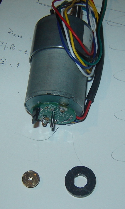
11-20-2012 01:14 AM
- Mark as New
- Bookmark
- Subscribe
- Mute
- Subscribe to RSS Feed
- Permalink
- Report to a Moderator
Hi hrh1818
I make some experiences without the motor right?
And with diferent pins I have values elapsed time between 4 and 6, depends on pins. What this means? Sorry, but I don´t understand your explanation.

11-20-2012 03:07 PM
- Mark as New
- Bookmark
- Subscribe
- Mute
- Subscribe to RSS Feed
- Permalink
- Report to a Moderator
Hi Everyone
Below is my changes in the dc motor (encoder) for counting only 1 pulse per revolution.
Later I will give you the results.
Below is a coin and magnetic "paper".
Then make a wall in the coin, cut a small piece of magnetic "paper" and glue it in the coin
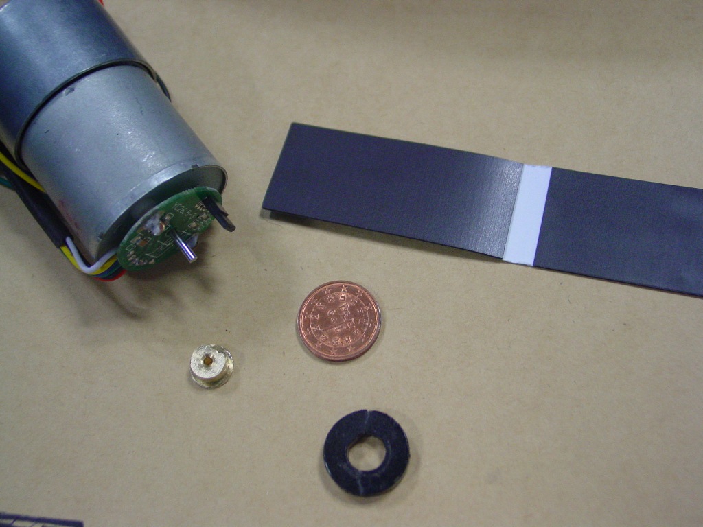

Voilá the final, later I will check, I need to re-solder the yelow wire...

king regards
cpalha
11-20-2012 06:45 PM
- Mark as New
- Bookmark
- Subscribe
- Mute
- Subscribe to RSS Feed
- Permalink
- Report to a Moderator
I don't understand why you get a variation in speed measurement with different digital pins and why some of the readings you obtained were much lower than my readings. Here are the readings I obtained with 9 different digial pins.
Digital Pin 2 > 7.9 seconds Digital Pin 3 > 7.9 seconds
Digital Pin 4 > 7.9 seconds Digital Pin 5 > 7.8 seconds
Digital Pin 6 > 7.9 seconds Digital Pin 7 > 7.9 seconds
Digital Pin 8 > 7.9 seconds Digital Pin 9 > 7.9 seconds
Digial Pin 10 > 7.9 seconds
All of the above readings were rounded off to 1 digit to the right of the decimal point.
It would help if other LIFA fans could report their speed test measurements.
With a 47.3 to one gear ratio the encoder shaft rotates at 11,825 RPM when the output shaft rotates at 250 RPM. This is approximately one revoutution in 5 milliseconds. You can not reliably detect one pulse every 5 milliseconds using LIFA. You wiil need to use an up/down counter to convert the pulse to a square wave and to reduce the frequency of the squre wave. With a 4 stage divide by 16 counter you can use Labview and LIFA to detect one rising edge transsistion for approximately every 1/3 of a revoution of the outpuut shaft.
Your modification to the encoder means we are back to when you said "I think it starts complicating.".
hrh1818
11-21-2012 05:55 AM
- Mark as New
- Bookmark
- Subscribe
- Mute
- Subscribe to RSS Feed
- Permalink
- Report to a Moderator
Hi hrh1818
I have donne the experiences in all pins.
2 - 6.36 3- 5.595 4 - 4.998 5 - 4.505 6 - 4.435 7 - 5.619 8 - 5.415 9 - 5.853
But if you repeat the test in the same pin many times, the time will be diferent.
"With a 47.3 to one gear ratio the encoder shaft rotates at 11,825 RPM when the output shaft rotates at 250 RPM" Is the inverse, when the gear box rotates a 11.825 rpm the encoder "rotates" a 250 rpm
You are right It starts complicating....
Best regards
cpalha
11-21-2012 11:49 PM
- Mark as New
- Bookmark
- Subscribe
- Mute
- Subscribe to RSS Feed
- Permalink
- Report to a Moderator
You say:
"But if you repeat the test in the same pin many times, the time will be diferent."
When I repeat the speed test on the same digital pin I have seen variations of as much as 0.15 seconds in the elasped time. It shouldn't make any difference but you could try running the test with the pin connected to ground.
You say:
"Is the inverse, when the gear box rotates a 11.825 rpm the encoder "rotates" a 250 rpm"
No. The data sheet for the motor says: "64 counts per revolution at motor shaft, which corresponds to 2797 counts per revolution at the gear box output shaft. Clearly the encoder shaft rotates many revolutions during one revolution of the gear box output shaft.
I made a mistake in my last message . The ratio of encoder to output shaft speed is 43.7 to 1 not 47.3 to 1. This mistake doesn't change the conclusion that when using LIFA you can not reliably detect 1 pulse per revolution of the encoder shaft.
What is the amplitude of the pulse produced with your modified encoder? Do you still get a 3 volt pulse at the lowest speed you plan on operating at?
11-22-2012 03:31 AM
- Mark as New
- Bookmark
- Subscribe
- Mute
- Subscribe to RSS Feed
- Permalink
- Report to a Moderator
Dear hrh1818
You are right once again.
I have changed the lenght of the magnetic tape, but even with this only measure the pulses correctly at slow speed.
I give up from this idea, I will mount everything and I will see where I can put the encoder or other to count pulses.
best regards
cpalha
11-22-2012 11:40 PM
- Mark as New
- Bookmark
- Subscribe
- Mute
- Subscribe to RSS Feed
- Permalink
- Report to a Moderator
I recommend you use the motor/encoder just like it was when you received it and use it with a quadratutre encoder IC.
Two examples of quadrature encoder ICs are
<http://documentation.renesas.com/doc/DocumentServer/S14940EJ3V0DS00.pdf>
<http://www.lsicsi.com/pdfs/Data_Sheets/LS7183_LS7184.pdf>
With the uPD you would need to use 2 additional ICs like this one:
<http://documentation.renesas.com/doc/DocumentServer/IC-3305A.pdf>
The uPD4702 and uPD4704 are onlyavailable on Ebay.
With the LS7184 you would need to use 3 additional ICs like this one:
This approach is not as intimidating as when I first suggested it because a VI for detecting riosing or falling edges is available for use with LIFA.
hrh1818
11-23-2012 12:12 AM
- Mark as New
- Bookmark
- Subscribe
- Mute
- Subscribe to RSS Feed
- Permalink
- Report to a Moderator
The LS7183 is to use alone?
I don't have hoppe that this resolve even that now I had made the experiences between ov and 5 volts from arduino. But I will use 12volts or lower a litle bit, so the speed will be much greater than now.
If the LS7183 is to use alone I buy one, if it is with more electronics......
cpalha
11-28-2012 01:28 PM
- Mark as New
- Bookmark
- Subscribe
- Mute
- Subscribe to RSS Feed
- Permalink
- Report to a Moderator
Hi hrh1818 and everyone
Today a make a change to count one pulse per revolution. I use a magnetic switch and a small magnetic piece.
Now it counts one pulse per revolution at maximum speed and don't loses pulses.
I put one digital pin send a 1 signal when the magnetic closes the switch another digital pulse receive the 1 signal and counts.
At the begining I have problems with noise, but with a resistor between digital pin in and gnd it resolves the problem.
Now I have conditions to develop my project and then I will give you the news about progress.
Best regards and thanks for all
cpalha


