- Subscribe to RSS Feed
- Mark Topic as New
- Mark Topic as Read
- Float this Topic for Current User
- Bookmark
- Subscribe
- Mute
- Printer Friendly Page
ERT
01-02-2008 11:53 AM
- Mark as New
- Bookmark
- Subscribe
- Mute
- Subscribe to RSS Feed
- Permalink
- Report to a Moderator
01-03-2008 02:41 PM - edited 01-03-2008 02:44 PM
- Mark as New
- Bookmark
- Subscribe
- Mute
- Subscribe to RSS Feed
- Permalink
- Report to a Moderator
Although I am not fully familiar with this application area, this sounds like something you should be able to implement with your hardware and software. Keep in mind that the link you provided is for a solution that other engineers have developed, which likely represents a considerable investment of time and resources. Reproducing a similar solution on your own will likely require a fair amount of work.
You can use your NI DMM to take measurements and advance through a scan list of channel connections on your SCXI-1127. Please have a look at the NI-SWITCH documentation and the following KnowledgeBase article: What are the scanning options for the SCXI-1127/1128 Switch Module? There are also example programs located in the NI Example Finder under "Hardware Input and Output >> Modular Instruments >> NI-SWITCH (Switches)". The examples here, especially the "niSwitch DMM" examples, should be useful for getting starting. Please keep in mind that the SCXI-1127 is unable to take simultaneous scans, so any ampersands ( & ) in your scan list will be treated as semi-colons if you are using NI-SWITCH 1.5 or earlier, or will return an error if you are using NI-SWITCH 1.6 or later.
Best of luck in your application!
Regards,
Message Edited by Devin_K on 01-03-2008 02:44 PM
01-03-2008 03:57 PM
- Mark as New
- Bookmark
- Subscribe
- Mute
- Subscribe to RSS Feed
- Permalink
- Report to a Moderator
Hai Devin
I am very glad to hear that I can do this experiment in labview, I got 2 multiplexers and I am using one for the channel scanning.As mentioned earlier I need to change the source and sink simultaneously ,I am doing this manually but rather I want to use another multiplexer for this operation . Is there any program like that that could automatically change my source and sink using multiplexer, if so please suggest me
Hope you respond soon and in the affirmative.
With regards
Madhava
01-04-2008 03:21 PM
- Mark as New
- Bookmark
- Subscribe
- Mute
- Subscribe to RSS Feed
- Permalink
- Report to a Moderator
Hi mady,
In skimming over the attached article, it seems that you want to select one electrode on one pipe as the source and one electrode on the other pipe as the sink. As long as the pipes remain as a source or sink, respectively, you are fine with using a multiplexer (MUX) configuration. You will need two SCXI-1127s in 1-wire 64x1 MUX mode, one for each pipe. Then the DMM would be used to measure the difference between the two voltages.
As mentioned you could start with the shipping example “niSwitch DMM Switch Synchronous Scanning.vi” and copy the Switch code portion to have a scan list for each switch. You would need to duplicate/cascade section A to initialize another scan list for the additional switch and duplicate/parallelize the code for section C to initiate the scan for both switches simultaneously. I’ve included the modified shipping example as a LabVIEW 8.0 file, but I received warnings that the toolkit Vis could not be saved to a previous version of LabVIEW, but they should work if you load it in a version of LabVIEW 8.0 or later as long as you have the toolkits necessary.
I hope that helps you get started.
Precision DC Product Support Engineer
National Instruments
01-09-2008 10:05 AM
- Mark as New
- Bookmark
- Subscribe
- Mute
- Subscribe to RSS Feed
- Permalink
- Report to a Moderator
Hai Mark,
It's a grea example code that you have provided, everything is fine, but my problem is that i need to change the source and sink.I would be giving some potential say 5 v to one of the electrode on pipe A that would act as my source electrode and the same voltage on the other pipe that is the negative teminal that would act as my sink electrode.Now I need to change this source and sink simultaneously, what i exactly mean that i would give the 5v voltage to each of the electrode and measure the remaining electordes potential values. So,how could I change this source and sink .The example code u have provided contains 3 blocks namely switch, dmm and resource name 2. so shall I use the switch block to change the source and sink, I would mention the electrode number in the scan list as "ch8->com0" supposing that electrode 8 is my source whether this could work or is there any other code that I could change my source and sink.
Hope you understand my query and resolve it .
Thanking you
madhava
01-10-2008 05:47 PM - edited 01-10-2008 05:48 PM
- Mark as New
- Bookmark
- Subscribe
- Mute
- Subscribe to RSS Feed
- Permalink
- Report to a Moderator
Hi mady,
I think you and I are talking about the same thing: you want pipe A to always be your source and pipe B to always be your sink. You want to connect any point on pipe A to any point on pipe B and have both points move at the same time. Correct?
If that’s the case, you just need to use both input lists and they will switch simultaneously. The DMM will wait for the time specified in “Sample interval (sec)” on the front panel before taking a measurement. For more details on how the VI works, please see the Example Finder’s description in the upper right. I only modified the example to include a second switch.
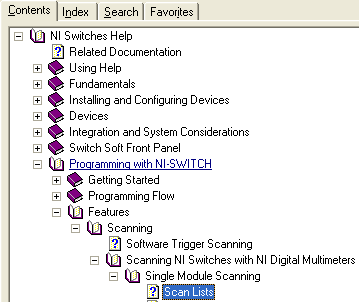
For the syntax on the scan list, please see the Switch Help file (Start » All Programs » National Instruments » NI-Switch » Documentation » NI Switches Help) and search for “scan list”.
Basically for pipe A, use one switch as chx->com and connect it to the DMM positive input and do the same thing for pipe B, but hook it to the negative input. The DMM will read the voltage potential between pipe A’s point and pipe B’s point.
If you need a more complex VI, we have Alliance members who can write that for you. You can visit them at ni.com/alliance. Good luck with your application.
Message Edited by Mark E on 01-10-2008 05:48 PM
Precision DC Product Support Engineer
National Instruments
01-14-2008 10:32 PM
- Mark as New
- Bookmark
- Subscribe
- Mute
- Subscribe to RSS Feed
- Permalink
- Report to a Moderator
Thanks for your great support in my experiment, initially I am doing only with one multiplexer as I am using a single source and sink. But probably I will be using 2 multiplexers in few days.I have got a small problem, so I have connected my second multiplexer in the last port of my chasis and my first multiplexer in my first port of chasis 1000
so when I tried to connect this configuration to the system I found out that I dont have another probe.But during my purchase i just got only the DMM that has one end to the chasis and the other end to the cpu that has four probes i also got a probe from monitor to the chasis 1000.Now could you please help me with connecting my second multiplexer. I probaly think that there is in an internal connection in the chasis . If I am wrong please help me in making this connection right and indicate the way how to exactly connect the 2 nd multiplexer
waiting for your apprehensive reply
Regards
Madhava
01-15-2008 03:17 PM
- Mark as New
- Bookmark
- Subscribe
- Mute
- Subscribe to RSS Feed
- Permalink
- Report to a Moderator
I think there may be some confusion with regards to terminology. I'm not sure what you mean by having a "probe from the monitor to the chassis." From what I understand, you have one DMM and two multiplexer switch modules, but you only have one probe. You would like to connect one terminal of the DMM to one multiplexer switch and a second terminal on the DMM to the other multiplexer switch.
You cannot connect the signals from the switch to the DMM internally. You will need to use an additional probe to make the connection. As Mark has mentioned in his previous post you can use one switch as chx->com for pipe A and connect it to the DMM positive input. Connect pipe B to the other switch module and connect com to the negative terminal of the DMM.
If I have misunderstood the issue, please clarify the description of the issue.
Best Regards
Hani R.
Applications Engineer
National Instruments
01-18-2008 02:47 PM
- Mark as New
- Bookmark
- Subscribe
- Mute
- Subscribe to RSS Feed
- Permalink
- Report to a Moderator
Hai NI,
It has been a great response from you ,thanks for your great support. All has been fine but it said that 1127 can switch the DC currents.Actyally I am giving an voltage of 12 v from a quad power generator ,I measured the current that is 0.2 amperes. So, I think that 1127 can handle this sort of current and I want to Know exactly how to switch this current that is generated by my power sourceto all the electrodes of my system. I am really confused about this , what I actually want is this I want to change my source and sink.I want to describe what my source and sink is the positive terminal of my power generator is going to one of my electrodes so that electorde shall act my source. The negative terminal goes to some elctrode and that would act as sink .
There are a total of 32 electrodes 16 on pipe1 and 16 on pipe2 .I ahve arranged such a way that all the 16 electodes on pipe1 are connected to my power genertor's positive terminal and the 16 electrodes on pipe2 are connected to power generator's negative terminal. Now , what I want is that electrode one should act as the source for some moment of time ( i.e.) it only should receive the power coming from power generator) that would act as the source for some moment of time say 10 secs and after that time the power should go to my second electrode like wise all the 16 electrodes.Similarly on the sink side.
It would be a great appreciation if you sort out me, Is there any VI that could do my job If so please provide me an example VI .
I would like to once again thank you for your great support in my experiment.
With regards
Madhava
01-21-2008 06:12 PM
- Mark as New
- Bookmark
- Subscribe
- Mute
- Subscribe to RSS Feed
- Permalink
- Report to a Moderator
Are you having trouble with the physical connections or with the creating the VI for your application. In the VI that Mark posted you can set the Sample Interval to 10s (Sample Interval sets the amount of time in seconds the DMM waits between measurements). Refer to the NI Developer Zone article How to connect signals to the SCXI-1127 for information about the physical connection.
Best Regards
Hani R.
Applications Engineer
National Instruments
