- Subscribe to RSS Feed
- Mark Topic as New
- Mark Topic as Read
- Float this Topic for Current User
- Bookmark
- Subscribe
- Mute
- Printer Friendly Page
- « Previous
- Next »
How to amplify thermocouple readings
09-27-2005 04:32 PM
- Mark as New
- Bookmark
- Subscribe
- Mute
- Subscribe to RSS Feed
- Permalink
- Report to a Moderator
09-27-2005 04:54 PM
- Mark as New
- Bookmark
- Subscribe
- Mute
- Subscribe to RSS Feed
- Permalink
- Report to a Moderator
09-27-2005 05:19 PM
- Mark as New
- Bookmark
- Subscribe
- Mute
- Subscribe to RSS Feed
- Permalink
- Report to a Moderator
09-28-2005 02:31 PM
- Mark as New
- Bookmark
- Subscribe
- Mute
- Subscribe to RSS Feed
- Permalink
- Report to a Moderator
09-29-2005 11:54 AM - edited 09-29-2005 11:54 AM
- Mark as New
- Bookmark
- Subscribe
- Mute
- Subscribe to RSS Feed
- Permalink
- Report to a Moderator
You have to get rid of the noise being induced by the 500KHz generator. No amount of oversampling or undersampling or grounding will fix your problem. In fact, extra grounding will probably make it worse. There are several ways to fix the problem:
Induction can only occure where there is a loop. If a 500KHz (or any frequency) square wave is run through a single wire, it will radiate an electrical field consisting of many harmonic frequencies well above 500KHz (the harmonics depend on the rise time of the square wave). To stop the radiation, you should either run the 500KHz through a coax or a twisted pair. If neither of these are happening, you have a large loop that can be described as starting from the 500KHz source and going to some ground plane that is physically separated from the actual signal physical path (wire or PCB trace). The larger the distance between the signal path and the signal return path (often called ground), the more radiated energy will be emitted by the loop. Coax or twisted pair will greatly reduce the problem.
If you can't fix the source of the radiation, then you can try to fix the susceptibility of the thermocouple circuit to induced voltages. Again, twisted pair wire should be used to connect the thermocouple to the amplifier. The wires should be twisted all the way to, or as close as possible to the amplifier. If the wire is twisted up to a connector on a PCB, and traces run the signal to the amplifier input, the traces on the PCB should be as close together as possible from the twisted pair connection to the amplifier differential input. (I hope you are using a differential amplifier). Any separation of wires or PCB traces will cause a loop that can pick up noise from any radiating source.
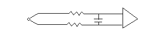
If you can't fix the close proximity of the PCB traces, you can try to put a balanced filter inline (see picture below). Put equal resistors (you will have to play with the values) inline with BOTH leads of the thermocouple. Put a capacitor (play with value) from the end of one resistor that goes to the amp to the end of the other resistor that goes to the amp. This method will not cut out as much of the noise as the first two methods above, but it may work.
Message Edited by tbob on 09-29-2005 10:55 AM
09-29-2005 12:34 PM
- Mark as New
- Bookmark
- Subscribe
- Mute
- Subscribe to RSS Feed
- Permalink
- Report to a Moderator
- « Previous
- Next »
