- Subscribe to RSS Feed
- Mark Topic as New
- Mark Topic as Read
- Float this Topic for Current User
- Bookmark
- Subscribe
- Mute
- Printer Friendly Page
Thermistor wiring in cb-68lp with PCI 6034E
10-11-2007 11:07 AM
- Mark as New
- Bookmark
- Subscribe
- Mute
- Subscribe to RSS Feed
- Permalink
- Report to a Moderator
10-12-2007 06:04 PM - edited 10-12-2007 06:04 PM
- Mark as New
- Bookmark
- Subscribe
- Mute
- Subscribe to RSS Feed
- Permalink
- Report to a Moderator
With NI-DAQmx and Measurement Automation Explorer there is actually a feature called connection diagram which will let you select your connection block and tell you exactly which pins you need to connect your sensor to, whether it is a thermistor or a thermocouple. You can actually set up a thermistor measurement in Measurement and Automation Explorer for current excitation and voltage excitation seperately.
For example, I created a current excitation thermistor task in Measurement and Automation Explorer running into ai0 (channel 0) and I clicked on the connection diagram tab at the bottom. Here is the diagram that I got.
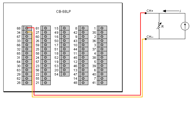
As you can see, you just need to connect to pins 68 and 34.
There is also an example program that you can download, which is in LabVIEW. Here it is.
Hope all this helps.
Regards,
Message Edited by Raajit L on 10-12-2007 06:05 PM
National Instruments
10-17-2007 02:33 PM
- Mark as New
- Bookmark
- Subscribe
- Mute
- Subscribe to RSS Feed
- Permalink
- Report to a Moderator
Bill
10-17-2007 03:29 PM
- Mark as New
- Bookmark
- Subscribe
- Mute
- Subscribe to RSS Feed
- Permalink
- Report to a Moderator
"It’s the questions that drive us.”
~~~~~~~~~~~~~~~~~~~~~~~~~~
10-17-2007 04:06 PM
- Mark as New
- Bookmark
- Subscribe
- Mute
- Subscribe to RSS Feed
- Permalink
- Report to a Moderator
As was previously mentioned, shielded twisted pairs are going to be important.
Lynn
10-18-2007 04:32 PM - edited 10-18-2007 04:32 PM
- Mark as New
- Bookmark
- Subscribe
- Mute
- Subscribe to RSS Feed
- Permalink
- Report to a Moderator
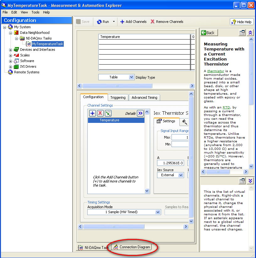
Looks like you did get all the steps right. The connection diagram tab is located at the bottom of the window. This screenshot should help.
Regards,
Message Edited by Raajit L on 10-18-2007 04:33 PM
National Instruments
10-19-2007 08:43 AM
- Mark as New
- Bookmark
- Subscribe
- Mute
- Subscribe to RSS Feed
- Permalink
- Report to a Moderator
10-22-2007 11:54 PM
- Mark as New
- Bookmark
- Subscribe
- Mute
- Subscribe to RSS Feed
- Permalink
- Report to a Moderator
Regards,
National Instruments
