LabVIEW

cancel
Showing results for 
Search instead for 
Did you mean: 

ontrak ADU200 usb sub vi?

To "Anyone better on this than me".
I bought a Relay USB device from OnTrak, http://www.ontrak.net/ADU200.htm supplied with an example LabView vi.
And it works fine in the Stand Alone (test) mode.
 
But can someone give me a hint on how to modify it in order to give commands and read the results "programmatically" from outside the "ADU Driver Stand Alone VI? (I.e. to turn it into a sub VI)? Attached. (Have asked OnTrak, but no help from them)
 
I have LabView 8.2 Base package and this does not include the used "Event Structure" (Not in Base Package, can be operated but with restrictions on modifications, unclear to me exactly how - it can be fiddled with and resaved but specific "Event Structure" commands like Add Case are not in menue)
 
I assume the same functionality can be acheived with the normal Case Structure function triggered on external conditions?
But when I do this convertion I get errors (lost threads to things controlled by a Property Node that i do not know how to resolve). And I am not even sure this is the way to go.
 
Any assitance appreciated. But please do not hint that I need to do a US$3000 upgrade to the Professional Version only for the reason to modify the Event Structure.
 
Thanks,
Tord K
0 Kudos
Message 1 of 6
(5,229 Views)
This is just an exercise in editing. Just copy the vi you posted orginal vi and rename it as something else and then edit it to what you want. Keep the orginal safe.
 
Use this as a guide line
 
Open the new file you just created
Right click on the while-loop and select remove while loop
If you want the code from the Command event case select it then drag it outside. This setting up which command parameters are valid depending on what command is going to be sent. I would suggest that this is not relevant as a sub-vi.
Make sure that you have Send:Value Change event case in view.
Right click on the edge event structure and select Remove event structure.
There will be a few bad wires but its all there.
After that you can setup up the connection panel at the top right of your front panel.
 
Make sense?
 
David
 
Message 2 of 6
(5,221 Views)
Tord K
 
Try this example
 
 
You could use this as your application template. It doesn't use events.
 
Hope this helps
 
David

Message Edited by David Crawford on 01-04-2007 02:58 PM

0 Kudos
Message 3 of 6
(5,211 Views)
David,
Thanks for reply.
The described method I think is the way I tried. But I became in doubt with how to correct the "errors" especially those coming from the output in the "Command" case.
 
The way it works in stand alone mode is to select a command (Eg. SK) and argument (0-3) from the predefined values which seem to set the NewValue parameter that triggers loading into the Command case.
 
 
Next step is to Order Send, also triggering NewValue. So both cases are required to complete any order tothe device.
 
I.e I already tried and copied relevant parts(?) into a new "normal" Case Structure, see attached.
But the errors are not just unneeded wires. The ones that concerns are the:
"Property Node: Contains bad or unwired teminal". Without further details I conclude these "indicators" are essential to be set correctly
 
So I will pursue this way to see if I can get things going.
In case of any further to this, thanks.
Tord K
 
 
0 Kudos
Message 4 of 6
(5,203 Views)

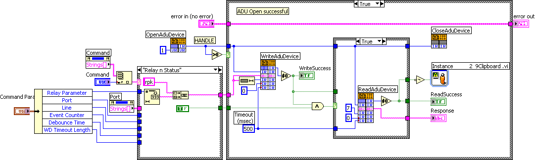
This is what David was telling you to do. There is absolutley no need for a case structure or anything else besides just what was inside the old 'Send' event and without the front panel 'Send" button.

Message Edited by Dennis Knutson on 01-04-2007 08:25 AM

Message 5 of 6
(5,202 Views)

David and Dennis,

Once again a big THANKS! It works exactly as you described.

Sorry for not understanding that the first response was complete, you see why I needed assitance ;-)!

Issue closed, I am back on track.

Tord K

0 Kudos
Message 6 of 6
(5,179 Views)