Shalom!
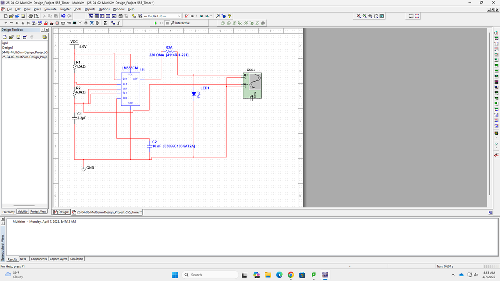
I have a question. We're in class using MultiSim 14.3. We're trying to bring the pic below from a MultiSim design to a physical breadboard:

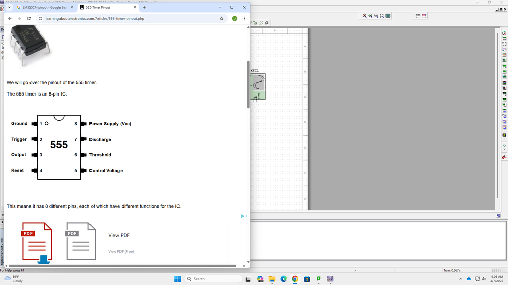
Our chip seen above, LM555CM, only has physical outputs at the pins (see pic below) while the design (pic above) shows outputs at the narrow ends where there are no pins.

To accomplish our task, I need to use the pic of the chip pinout below, which completely changes the circuit design. This makes building this circuit confusing.

My question is, is there a way to change the chip display in MultiSim to match the real world pinout of the chip without having to download the real world pinout and translate between the two?
Thanks,
Jeff G.