- Subscribe to RSS Feed
- Mark Topic as New
- Mark Topic as Read
- Float this Topic for Current User
- Bookmark
- Subscribe
- Mute
- Printer Friendly Page
Engine Simulation Custom Device Feedback
07-19-2013 10:12 AM
- Mark as New
- Bookmark
- Subscribe
- Mute
- Subscribe to RSS Feed
- Permalink
- Report to a Moderator
Hi Jamesy,
I've reviewed this information and have some discussion here.
First, one thing that is annoying about the engine simulation custom device for N teeth M missing is that instead of picking which teeth are missing, you specify at which angle are there missing teeth. The custom device translates this into a mask of low values based upon the degree width of teeth. It makes sense but its hard to use. In the future I want to change this. So if you have 60 teeth, each tooth is considered 6 degrees (3 high 3 low). Then, if you picked the location of missing teeth to be lets say... 12 degrees and 1 missing tooth. Then a mask is applied of low values between the start of degree 12 and 17 (inclusive, 6 degrees total). Therefore it is easy to configure "half teeth" like you did in slides 2-4.
Since you have set the # of teeth to be 60, missing teeth to be 2, and the location of missing teeth to be 268, it created a mask in the appropriate spot to create two "half teeth". Because the mask started in the middle of one tooth and finished in the middle of another. You can see this mask moving by setting the missing teeth location up and down from 268. Use your keyboard to press up/down and see it move. The 45th tooth goes from 267-269, gap 270-272, 46th tooth 273-275, gap 276-278, 47th tooth 279-281 (all #s inclusive). Since your mask was 12 degrees, you forced degrees 268-279 (inclusive) to low. Therefore you had one degree of tooth 45, none of tooth 46, and two degrees of tooth 47.
I realize this is really confusing and I hope to change this to just specifying which teeth are missing in the future.
Therefore with that information, look again at slide #3 and #4. The line you have marked as the 283 degree line is not 283 degrees. From above, we know that after the gap, there is the last two degrees of tooth 47. Tooth 47 is high at degrees 279, 280 and 281. Its first degree is masked to low, so the first high degree is 280. So that is actually the 280 degree line, which means there is zero degrees of error.
On slide 5 you added 3 degrees. Which moves the mask and now forces degrees 271 to 282 (inclusive) to low. That means all of tooth 46 and 47 are masked low, so the next tooth is 48 which spans from 285-297 (inclusive). So at the bottom of slide 5 you say TDC is "283 degrees this way" That is incorrect it should be 285 degrees. Therefore the two degrees of error you noted is actually 0.
I hope this helps!
07-23-2013 07:34 PM
- Mark as New
- Bookmark
- Subscribe
- Mute
- Subscribe to RSS Feed
- Permalink
- Report to a Moderator
Hi Stephen,
Thanks for the info. I was able to use a scope and find values that synced with my ecu. I now have less than 2 degrees of error which is great.
Next problem: My ECU actuator (fuel injector) readings are +/- 360 degrees before TDC. (NI veristand is 0-720 after TDC)
So i want to scale the "start angle" and "end angle" variables in the fuel injector VI. The equation is simple;
720 degrees - the original NI start angle.
If that value is > 360 then take away 720 from it.
I've did that in the VI.
I tapped off a line from the original angle values and performed the equation.
I added two new variables to store the result and re-assigned the existing terminals to referece my 2 new variables.
Problem: I seem to still get the old angles.
Can you see anything I've did wrong?
Perhaps i should tap off the original values outside the case statement and then scale them?
I wasnt able to connect one of my new locals to my new scaled value as NI gave an error. ( i was trying to match the original code method which is still fully intact in the VI)
James
07-23-2013 09:14 PM
- Mark as New
- Bookmark
- Subscribe
- Mute
- Subscribe to RSS Feed
- Permalink
- Report to a Moderator
Hi Stephen,
Attempt 2 :
I tried to run a wire off the original NI Veristand Start and end angles ( This time outside the case statement ).
The good news is that the first part of my scaling works ( 720 - NI veristand original value )
The problem is that when my case statement check for > 360 goes true i should take 720 degrees aways from the value.
instead of -360 i am seeing 664.1 degrees. 361-720 should = -360 approx.
Is this because of the type of the variable in labview??
James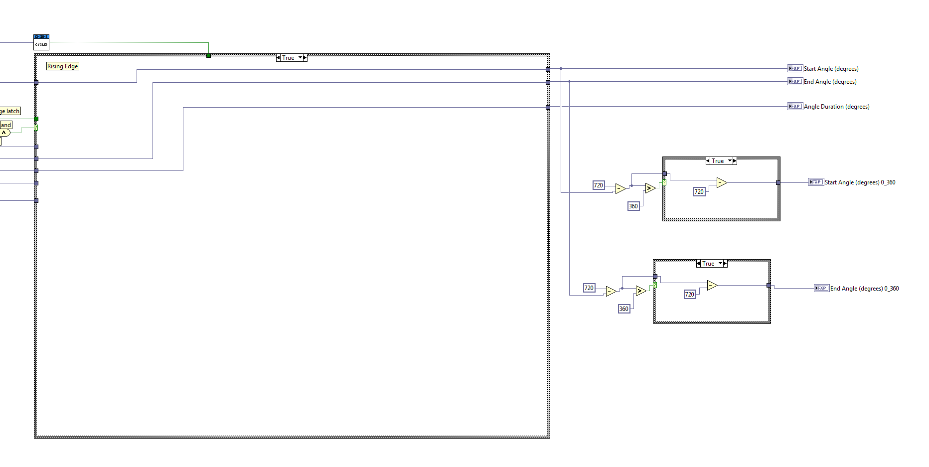
07-24-2013 09:38 AM
- Mark as New
- Bookmark
- Subscribe
- Mute
- Subscribe to RSS Feed
- Permalink
- Report to a Moderator
Hey Jamesy,
I'm glad you were able to sync with the ECU. I'm curious why you still have 2 degrees of error. Did my commentary from before make sense? It should show there is no error from the simulator side.
The problem you're seeing is the FXP data types for start angle and end angle are expected to be unsigned, as the original outputs are. So those values cannot go negative. When using + and - nodes, you can right click them and configure what the resultant data type is... but the default after doing subtraction will be signed. So your math has changed the FXP data types from their previously unsigned state to now be signed.
So the value in the FPGA is correct then. you're not doing anything wrong in the FPGA... but the custom device is reading that value as a U64 and then translating it back to the originally expected data type of unsigned. Therefore the value the custom device sees is different than what the FPGA actually has.
The custom device code to read the values (as U64s) and change them to FXP data type is inside "\Engine Simulation\Source\Real-Time\Utility\FPGA Output Read.vi":

See there where it reads crank angle, start angle, and end angle... it reads the u64 and then uses integer to FXP cast with a FXP data type of +,61,10. But your modifications to the FPGA code has changed that data type. SO you will need to change the FXP cast data type in this custom device VI to match. Note this VI's case structure is for crank angle, start angle, and end angle... you will want to split this into two cases (one for crank which is unmodified, one for start/end which is modified) because you haven't changed the crank angle data type. When you're done, rebuild the custom device engine.
A different approach that might be a lot easier is to simply do this with a calculated channel or model inside NI VeriStand instead of changing the value at the FPGA before it gets to NIVS.
07-24-2013 01:33 PM
- Mark as New
- Bookmark
- Subscribe
- Mute
- Subscribe to RSS Feed
- Permalink
- Report to a Moderator
Hi Stephen,
Its unclear where the error is, its actually more like <1 degree error so I'm happy to move forward.
option 1: Custom device mod...
I haven't altered the custom device before this sounds risky, especially as everything is working well right now.
If you could give me some guidelines maybe I'll attempt this.
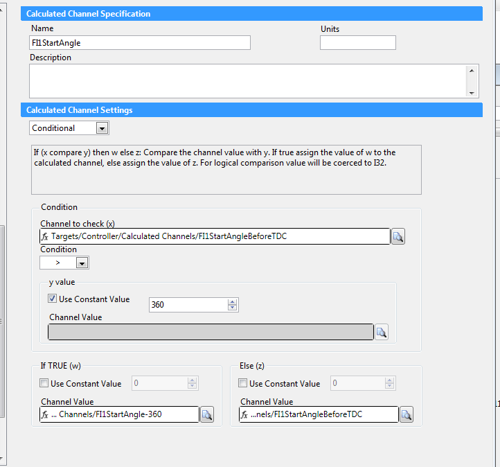
option 2: calculated channel..
I think i can use a calculated channel. I'm going to try this out.
Question: Once the angles find their way into veristand, are they signed values? ie can i then go less than 0 ? so 360-720 will == -360 ??
regards
James
07-24-2013 01:34 PM
- Mark as New
- Bookmark
- Subscribe
- Mute
- Subscribe to RSS Feed
- Permalink
- Report to a Moderator
Yes they are doubles at that point. Calculated channels should work
07-24-2013 01:44 PM
- Mark as New
- Bookmark
- Subscribe
- Mute
- Subscribe to RSS Feed
- Permalink
- Report to a Moderator
My method has 3 calculated channels per event . thats 192 additional calculated channels in my system.
Any limitations of doing this? ( apart from being a lot of manual work)
Am i now removing the angle processing from my FPGA ?
So when i log angles v time will I'll see some perfomance issues?
James
07-24-2013 02:01 PM
- Mark as New
- Bookmark
- Subscribe
- Mute
- Subscribe to RSS Feed
- Permalink
- Report to a Moderator
Yeah... I'm sorry to hear that. Calculated channels are pretty cumbersome to use. And yes, this will have some performance impact. As long as you have them executed in the correct order... I think you will have a 1 cycle delay from when the custom device value updates to when the calculated channel value updates. It might be 2 cycle. I dont remember. You could log it and see.
You are still doing the angle detection in the FPGA. you're just transforming the value some when it comes into CPU.
The "cleanest" way to do this is inside the custom device. But I agree. it would not be fun to branch the custom device code so you can't easily update when I make a new revision.
We are working on a custom device that will allow reading any control/indicator from FPGA and bringing it into a channel inside NI VeriStand... but that isn't done yet.
Next best thing would be to create a model. you can create one in labview very easily and just import it to NIVS in a few clicks.
http://www.ni.com/white-paper/11135/en
You would probably want just one input array and one output array. Then just do the same math you were doing on the FPGA right inside the model. Attached is a VI that would do it. just compile it into a model
07-24-2013 02:02 PM
- Mark as New
- Bookmark
- Subscribe
- Mute
- Subscribe to RSS Feed
- Permalink
- Report to a Moderator
That is saved in 2012. let me know if I should save it back further
07-24-2013 03:55 PM
- Mark as New
- Bookmark
- Subscribe
- Mute
- Subscribe to RSS Feed
- Permalink
- Report to a Moderator
2012 is fine.
When i click on tools i dont have a "veristand option"
I have full veristand 2012 installed.
Is the Model framework and model support something that doesnt come with veristand?
How can i tell if its installed and if its not where can i get it?
James.
