- Subscribe to RSS Feed
- Mark Topic as New
- Mark Topic as Read
- Float this Topic for Current User
- Bookmark
- Subscribe
- Mute
- Printer Friendly Page
PID Derivative Gain
10-14-2013 06:05 PM
- Mark as New
- Bookmark
- Subscribe
- Mute
- Subscribe to RSS Feed
- Permalink
- Report to a Moderator
10-16-2013
07:05 PM
- last edited on
11-13-2024
03:39 PM
by
![]() Content Cleaner
Content Cleaner
- Mark as New
- Bookmark
- Subscribe
- Mute
- Subscribe to RSS Feed
- Permalink
- Report to a Moderator
Here is the online help documentation for the LabVIEW PID and Fuzzy Logic Toolkit:
More specifically you might be interested in this topic:
If you are looking for a tutorial that explains how PID derivative gain works and how to tune a PID control system, you might be interested in this white paper.
https://www.ni.com/en/shop/labview/pid-theory-explained.html
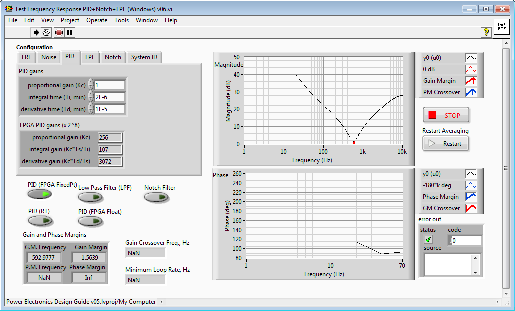
If you want to understand how derivative gain effects the frequency response of your control system, you might also be interested in the Power Electronics Design Guide example "Test Frequency Response PID+Notch+LPF (Windows) v06.vi". It's located in the LabVIEW Project under My Computer>IP Cores - LabVIEW FPGA>Control & Signal Gen>Testbench.
As you can see below, with this particular combination of PID gains, a derivative time of 1E-5 minutes, causes the gain of the PID control system to increase at frequencies above 595 Hz.
Now let's increase the derivative gain two orders of magnitude to 1e-3. Notice that now the high frequency gain is actually greater than the DC gain of the control system. This is the main challenge you'll run into with derivative gain-- it amplifies high frequency noise. In this case, since the high frequency gain is greater than the DC gain you are almost gauranteed the control system will be unstable.

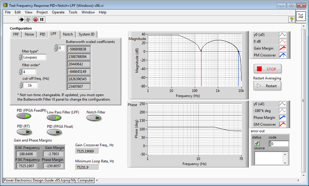
Okay, but what if we need derivative gain at lower frequencies to add damping to the control system-- effectively acting like a resistor at higher frequencies? How about addind a low pass filter in series with the PID control system? Here we have the same PID gains as above but we've added a 4th order low pass filter with a cutoff frequency of 1 kHz. See how the gain of the control system rolls off above 1 kHz and doesn't go above the DC gain. Furthermore, the derivative action gives us damping between 189 Hz and 1 kHz.