- Subscribe to RSS Feed
- Mark Topic as New
- Mark Topic as Read
- Float this Topic for Current User
- Bookmark
- Subscribe
- Mute
- Printer Friendly Page
Synchronizing 4 SCXI-1140 Modules
05-27-2008 10:31 AM
- Mark as New
- Bookmark
- Subscribe
- Mute
- Subscribe to RSS Feed
- Permalink
- Report to a Moderator
05-28-2008 04:43 PM
- Mark as New
- Bookmark
- Subscribe
- Mute
- Subscribe to RSS Feed
- Permalink
- Report to a Moderator
Hi avasque2,
To have an E-Series DAQ card control each SCXI-1140 and then synchronize them you will need to do several things. The first is to set each SCXI-1140 to communicate in parallel mode. This will allow each of the DAQ cards to sample from one of the SCXI-1140’s. Each of the DAQ card will need to be wired to the back of the SCXI module it is sampling from. One of the DAQ cards will also be the controller for the chassis. Some instructions for setting this up can be found here.
Once the chassis is configured you will then need to sync the four DAQ cards. This can be done by have one of the four cards generate the sample clock and start trigger and share them through the PXI backplane. The other three cards will use the sample clock and start trigger to stay synced. An example and explanation of how to do this can be found in the Developer Zone article, M Series Synchronization with LabVIEW and NI-DAQmx. Since you are using E-Series DAQ you will want to look at the section towards the bottom of the article titled, An Alternative Method: Synchronization by Sharing a Sample Clock.
Please let me know if you have any questions.
Thanks,
NI Chief Hardware Engineer
05-29-2008 03:32 PM
- Mark as New
- Bookmark
- Subscribe
- Mute
- Subscribe to RSS Feed
- Permalink
- Report to a Moderator
06-13-2008 12:56 PM
- Mark as New
- Bookmark
- Subscribe
- Mute
- Subscribe to RSS Feed
- Permalink
- Report to a Moderator
06-16-2008 07:48 PM
- Mark as New
- Bookmark
- Subscribe
- Mute
- Subscribe to RSS Feed
- Permalink
- Report to a Moderator
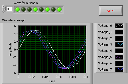
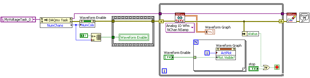
Attached is a simple example that demonstrates how you can dynamically change which channels are displayed on a waveform graph. You can also modify this VI to only allow static changes prior to graphing. To do this, simply move the FOR loop outside of the While loop and delete the array initialization procedure. Let me know if you have any questions!
06-17-2008 10:25 AM
- Mark as New
- Bookmark
- Subscribe
- Mute
- Subscribe to RSS Feed
- Permalink
- Report to a Moderator
06-17-2008 10:29 AM
- Mark as New
- Bookmark
- Subscribe
- Mute
- Subscribe to RSS Feed
- Permalink
- Report to a Moderator
06-17-2008 01:03 PM - edited 06-17-2008 01:09 PM
- Mark as New
- Bookmark
- Subscribe
- Mute
- Subscribe to RSS Feed
- Permalink
- Report to a Moderator
Unfortunately, I do not have DAQmx support installed for LabVIEW 7.0, so here are the screenshots:
Front Panel while running:
Block Diagram:
Message Edited by Pakman on 06-17-2008 01:09 PM
06-18-2008 12:46 PM
- Mark as New
- Bookmark
- Subscribe
- Mute
- Subscribe to RSS Feed
- Permalink
- Report to a Moderator
06-18-2008 12:47 PM
- Mark as New
- Bookmark
- Subscribe
- Mute
- Subscribe to RSS Feed
- Permalink
- Report to a Moderator
