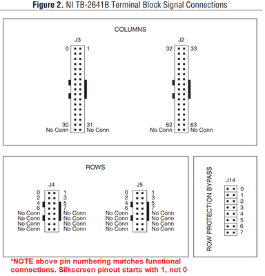
The TB-2641B Installation Instructions (and others of the same family) references the pins of J2, J3, J4, and J5 in functional way (that is, starts with pin 0 on each connector.) However, the actual silkscreen starts with pin 1 on each connector (J2, J3, J4, J5.)
This inconsistency makes it difficult to specify which pin goes where in cable drawings, since anyone looking at the physical hardware sees different pin identifiers than was planned for via the documentation. In a worst case, this could cause power-to-ground or other shorts that damage hardware because the engineer specified one thing in a drawing, and a technician wired up something else.
Any plans on correcting either the silkscreen or the documentation? At least having a note within Figure 2 to indicate the silkscreen differs from the pin descriptions there would help...
