- Subscribe to RSS Feed
- Mark Topic as New
- Mark Topic as Read
- Float this Topic for Current User
- Bookmark
- Subscribe
- Mute
- Printer Friendly Page
Digital input
09-13-2006 12:00 PM
- Mark as New
- Bookmark
- Subscribe
- Mute
- Subscribe to RSS Feed
- Permalink
- Report to a Moderator
09-14-2006 01:30 PM
- Mark as New
- Bookmark
- Subscribe
- Mute
- Subscribe to RSS Feed
- Permalink
- Report to a Moderator
I am not sure I fully understand the question. An input high voltage is considered anything between 2.0V and 5.0V and an input low voltage is considered anything between 0V and 0.8V. These levels are not adjustable in the DAQPad-6016. An external resistance does not really determine whether an input is read high or low unless you were feeding that resistance with a known current. Please tell me more about your application and I will help you in any way that I can.
Regards,
Jeff Tipps
Applications Engineer
National Instruments
09-14-2006 01:45 PM
- Mark as New
- Bookmark
- Subscribe
- Mute
- Subscribe to RSS Feed
- Permalink
- Report to a Moderator
09-14-2006 02:25 PM - edited 09-14-2006 02:25 PM
- Mark as New
- Bookmark
- Subscribe
- Mute
- Subscribe to RSS Feed
- Permalink
- Report to a Moderator
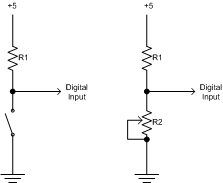
When you detect a switch closure, you have a circuit as shown on the left in that attached drawing. R1 may be a resistor than is on the DAQ board or you may have to provide it externally. I don't know about your model of DAQ board but it should be in the specs somewhere. The detection of an open or close is pretty straight forward as the input to the digital line is either pulled up to 5V or is at gnd. The value of R1 is not all that important. When you replace thw switch with a pot, then you have a voltage divider and the voltage at the digital input will have to be calculated with ohm's law and the value of R1 needs to be known. Once you know that, then you should be able to calculate what value of R2 will give you a voltage greater than 2V or less than .8. Anything in between will be indeterminate.
Message Edited by Dennis Knutson on 09-14-2006 01:27 PM
09-15-2006 03:43 AM
- Mark as New
- Bookmark
- Subscribe
- Mute
- Subscribe to RSS Feed
- Permalink
- Report to a Moderator
An input is supposed to be high if the voltage is more than 2.3V and if the voltage source can supply more than 40uA at this voltage rating.
However, with most TTL-compatible CMOS circuitry (which is used in most cases today) the (positive or negative) input currents do not matter much anymore. The inputs of a CMOS circuit are (almost) purely voltage-driven. It should be possible to tie a CMOS input to low level even with a rather high resitor value since almost no current will flow through the resistor.
Anyhow, whether you are dealing with true TTL inputs or TTL-compatible CMOS inputs it is not very wise to tie the input to ground via a resistor. Such a resistor will always cause high impedance of the input line, making it prone to radiated noise. In case of a true TTL input a resistor tied to ground will rise the input voltage and hence decrease the safety margin (i.e. the difference between required an actual low level voltage). The resistance between the input and ground should be as low as possible in the low level state.
So do yourself a favor and do NOT use any resistors (variable or not) to tie the input to low level. Even if you find a suitable resistor value usually it is not guaranteed that this value will work properly with the next device (or in a different environment) since current(s) in the low level state are not very well defined and since the increased sensitivity for radiated noise might cause trouble.
If you need something like resistor value detection or voltage level detection it will be much better to use either an analog input with proper level detection or to use additional input circuitry with well defined voltage level trigger specifications (AKA comparator circuit). Since the latter usually is not needed when designing digital circuitry do not expect such a feature on a digital I/O board.
