- Subscribe to RSS Feed
- Mark Topic as New
- Mark Topic as Read
- Float this Topic for Current User
- Bookmark
- Subscribe
- Mute
- Printer Friendly Page
Coloring a 3D Graph using measured Data
11-08-2012 07:49 AM
- Mark as New
- Bookmark
- Subscribe
- Mute
- Subscribe to RSS Feed
- Permalink
- Report to a Moderator
Hey there,
at first: Sorry for my "bad" english...I dont even know how to explain my problem in german, so english will be tough 😉
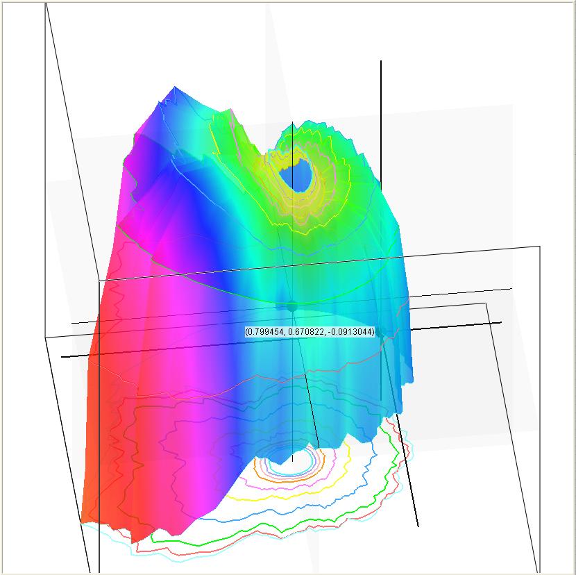
I made a programm that can read the coordinates of NC Programms (X,Y,Z) and plots it into a 3D Graph (so I am plotting an five achsis milling process). This works fine. But: I have an array full of Data that has been measured while milling (e.g. acoustic emission, cutting forces..etc). I have to color the 3D Plot using this measured data.
For Example: While milling the cutting forces raises and the plot should color using the cutting forces from green to red (green: cutting forces below certain limit, red above). So when I read the coordinates/the plot (which describe the contour the tool runs) I can see by its color if everything (the measured process parameter) is fine.
I checked the 3D Plot's color vector but I just didnt get how it works. I read that the coloring is mostly affected by the Z- Coordinates (If it would be just affected by the color vector itself!)
I hope I could describe my problem properly. Thanks & best regards
Bastian
11-09-2012 08:50 AM
- Mark as New
- Bookmark
- Subscribe
- Mute
- Subscribe to RSS Feed
- Permalink
- Report to a Moderator
Hello Bastian,
maybe it would be easier for other people to imagine your question, if you coul deliver a picture or maybe a video, what you want to archive.
Do you allready tried to create a programm in LabVIEW for your task? If yes, could you provide this programm?
Regards, Stephan
11-09-2012 09:04 AM
- Mark as New
- Bookmark
- Subscribe
- Mute
- Subscribe to RSS Feed
- Permalink
- Report to a Moderator
11-12-2012 05:57 AM
- Mark as New
- Bookmark
- Subscribe
- Mute
- Subscribe to RSS Feed
- Permalink
- Report to a Moderator
Hello Sebastian,
I think that I understand your question. I don't tried somithing like that by myself. Maybe the following Link could help you
Community: 4D Plot, a 3 degree of freedom accelerometer data with respect to time
https://decibel.ni.com/content/docs/DOC-9291
This is an example, how you can display 4D-Data in LabVIEW.
Stephan
11-12-2012 08:22 AM
- Mark as New
- Bookmark
- Subscribe
- Mute
- Subscribe to RSS Feed
- Permalink
- Report to a Moderator
Check out this thread for an index of examples.
The link for this image can serve as a tutorial.
ANd the link for this one can serve as a "Lab exercise" to help you get familiar with how the various components work together.

Have fun!
Ben
11-14-2012 12:54 AM
- Mark as New
- Bookmark
- Subscribe
- Mute
- Subscribe to RSS Feed
- Permalink
- Report to a Moderator
Thanks for the nice examples, I think the 4D Accelerometer Plot looks very promising.
But I have never worked with such a complex structure just for visualizing something. On the first view I do not really get how this piece works or how I can change it for my purpose. Is there any kind of tutorial in this matter?
Thanks again guys!
Bastian (actually just Bastian, I never got the "Se" 😄 )
11-14-2012 02:45 AM
- Mark as New
- Bookmark
- Subscribe
- Mute
- Subscribe to RSS Feed
- Permalink
- Report to a Moderator
Its me again.
I just used try and error at the 4D Acc example and somehow I made it work. BUT:
I just can use this settings, otherwise the lines are combined or the surface just doenst work (if I choose this).
PointStyle: cwPoint3DSolidCircle (I can use other Point structures, but this one looks the best)
PointColor: It set onto blue, but has no effect
LineStyle: no actual effect (what does it?)
LineColor: the same
ContourLevels: Whats this feature?
PlotStyle: cwPoint
Transparency: 20
Can anyone explain to me what these name features acutally do?
The result is not quite bad, the plotted Points change their color dependend on the W-Vector (I just filled one with 0 and replaced 2 values, so that only 2 Points will me Colored).
But the result would be nicer if I dont see any points, but a line which is colored. I didnt find any working combination of the possible settings.
Again thank you very much, 90% of the work are done *happy*
11-14-2012 07:24 AM
- Mark as New
- Bookmark
- Subscribe
- Mute
- Subscribe to RSS Feed
- Permalink
- Report to a Moderator
@man1ac wrote:
Its me again.
I just used try and error at the 4D Acc example and somehow I made it work. BUT:
I just can use this settings, otherwise the lines are combined or the surface just doenst work (if I choose this).
PointStyle: cwPoint3DSolidCircle (I can use other Point structures, but this one looks the best)
PointColor: It set onto blue, but has no effect
LineStyle: no actual effect (what does it?)
LineColor: the same
ContourLevels: Whats this feature?
PlotStyle: cwPoint
Transparency: 20
Can anyone explain to me what these name features acutally do?
The result is not quite bad, the plotted Points change their color dependend on the W-Vector (I just filled one with 0 and replaced 2 values, so that only 2 Points will me Colored).
But the result would be nicer if I dont see any points, but a line which is colored. I didnt find any working combination of the possible settings.
Again thank you very much, 90% of the work are done *happy*
Well the other 10% is something you will have to get yourself by playing with the various options.
Line setting only have an effect if you are using a plot with line.
Point color is derived from the W vector and the color mapping.
Contour levels will draw lines throug hte surface where the Z plane intersect the surface.
I never got the help to work corectly and lerned everything I know by playing with the code.
Have fun!
Ben
11-14-2012 07:28 AM
- Mark as New
- Bookmark
- Subscribe
- Mute
- Subscribe to RSS Feed
- Permalink
- Report to a Moderator
Isnt there any possibility to edit my posts? Hopefully I do not upset on of the moderators in here. If so: I am sorry, would you please merge my last posts into one? Thanks!
Up to topic:
Although I can only show Points in a way they are meaningful I noticed something strange:
My Coloring-Signal (e.g. cutting force - but doesnt matter) has some kind of offset and a noise overlay. I changed the three coloring options to this:If the soundlevel (cutting force, whatever) is good (If my coloring signal is below 100 (just an example) the points should be colored green. If the value is around (or exact) 125 the points should be blue. If a value above 150 is found, the points should color red.
If the point's value is exactly 100/130/150 the coloring works fine.
But because its a noise signal it is mostly (99%) just around these values. So the points color themselfs eg. a value of 140 purple. I do not really understand how the coloring works, because I thought if most values are below 100 they should be green, but they arent.
Hopyfully you guys understand what I mean.
I tried to fix the problem with a (quite bad, because I cant notice any tendency development (meaning the line colors itself more and more red). I check the noise/color signal and change the values (If >150, change it to 150; if <150 AND >130 set it to 130 and if below 130 set to 100) so that they are exactly the same as my coloring range.
Thanks again, just to write this down helps a bit 🙂
11-14-2012 07:34 AM
- Mark as New
- Bookmark
- Subscribe
- Mute
- Subscribe to RSS Feed
- Permalink
- Report to a Moderator
I beilieve there is a option for the colors to NOT ramp between values.
ben
