- Subscribe to RSS Feed
- Mark Topic as New
- Mark Topic as Read
- Float this Topic for Current User
- Bookmark
- Subscribe
- Mute
- Printer Friendly Page
- « Previous
-
- 1
- 2
- Next »
Do I need additional hardware to control solenoids?
10-17-2005 07:16 PM
- Mark as New
- Bookmark
- Subscribe
- Mute
- Subscribe to RSS Feed
- Permalink
- Report to a Moderator
10-17-2005 09:43 PM
- Mark as New
- Bookmark
- Subscribe
- Mute
- Subscribe to RSS Feed
- Permalink
- Report to a Moderator
I would wire each channel of my DIO to a diode, then from the diode to a relay coil. The other side of the coil would go to ground. The common would wire to the power supply (which I set to output 12VDC?). The normally open contact wires to the solenoid. The other side of the solenoid goes to ground. I leave normally closed wired to nothing.
Is this setup correct?
10-18-2005 01:40 AM
- Mark as New
- Bookmark
- Subscribe
- Mute
- Subscribe to RSS Feed
- Permalink
- Report to a Moderator
Hi,
A lot of good suggestion and (basic) electronics here. Before you buy everything you think you need; I saw the solenoid on a website but no datasheet. Do you know how much current the solenoid needs. If it's below 1A then you can use the solutions mentioned but if it is several amps you should be careful in choosing the right components.
Do you have more information about the solenoids ?
10-18-2005 11:30 AM - edited 10-18-2005 11:30 AM
- Mark as New
- Bookmark
- Subscribe
- Mute
- Subscribe to RSS Feed
- Permalink
- Report to a Moderator
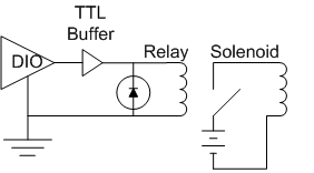
Jonzaeta: Your description is not quite accurate. I guess a picture is worth a thousand words. Here is a schematic of how it needs to be wired. Be sure to connect the diode with the polarity as shown. If your DIO can supply enough current to drive the relay, you can omit the TTL Buffer. You need to check the specs to be sure. Also be sure the power supply can handle the current required by the solenoid. Sometimes a simple wall pack (little square plastic box that plugs right into the wall socket) can be used for a power supply if the current drain is low enough.
Message Edited by tbob on 10-18-2005 10:31 AM
10-18-2005 12:19 PM
- Mark as New
- Bookmark
- Subscribe
- Mute
- Subscribe to RSS Feed
- Permalink
- Report to a Moderator
Thanks everyone for the help. It's quite a learning experience for me to work on this project.
07-11-2006 02:26 PM
- Mark as New
- Bookmark
- Subscribe
- Mute
- Subscribe to RSS Feed
- Permalink
- Report to a Moderator
I could suggest a TI quadruple half-h driver, model number SN754410. I use this driver currently to control 2 24V cole parmer solenoid valves. It has a voltage range of 4.5V to 36V so could easily power your valves. This drivers inputs are compatable with TTL-logic. The question remains as to you needing multiple solenoids to be powered. Maybe several can be interconnected or even kept seperate but with a common power input?
Good luck!
Daniel
07-11-2006 02:45 PM
- Mark as New
- Bookmark
- Subscribe
- Mute
- Subscribe to RSS Feed
- Permalink
- Report to a Moderator
07-11-2006 02:50 PM
- Mark as New
- Bookmark
- Subscribe
- Mute
- Subscribe to RSS Feed
- Permalink
- Report to a Moderator
- « Previous
-
- 1
- 2
- Next »
