- Subscribe to RSS Feed
- Mark Topic as New
- Mark Topic as Read
- Float this Topic for Current User
- Bookmark
- Subscribe
- Mute
- Printer Friendly Page
How do I measure frequency with AT-mio-16E-1 and BNC-2090?
04-02-2008 10:24 AM
- Mark as New
- Bookmark
- Subscribe
- Mute
- Subscribe to RSS Feed
- Permalink
- Report to a Moderator
04-03-2008 12:21 PM - edited 04-03-2008 12:22 PM
- Mark as New
- Bookmark
- Subscribe
- Mute
- Subscribe to RSS Feed
- Permalink
- Report to a Moderator
Hello Vr6Fidelity,
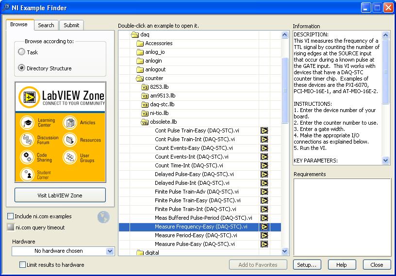
I would suggest looking at page 3-22 of the AT-MIO-16 User Manual for information on how to make a frequency measurement with the AT-MIO-16E-1. There is also information on page 2-13 of the BNC-2090 User Manual on how to access the counters on your MIO board through the BNC-2090. As far as the VI's you should use go I would suggest looking in the example finder. To access the example finder open LabVIEW and then go to Help>> Find Examples... Once the example finder window comes up you should be able to find Traditional DAQ examples for the AT-MIO-16E-1 board by clicking on "Directory Structure" and then navigation to the folder shown in the image below.
I hope this helps get you started.
Cheers,
Message Edited by Brooks_C on 04-03-2008 12:22 PM
04-03-2008 01:26 PM
- Mark as New
- Bookmark
- Subscribe
- Mute
- Subscribe to RSS Feed
- Permalink
- Report to a Moderator
04-04-2008 12:59 PM - edited 04-04-2008 01:00 PM
- Mark as New
- Bookmark
- Subscribe
- Mute
- Subscribe to RSS Feed
- Permalink
- Report to a Moderator
Hello Vr6Fidelity,
If you're measuring a 50 kHz signal with the counter then the measurement should be much more accurate than 10%. The card compares the source (a known frequency from one of the card's timebases) to the incoming frequency and then calculates the period that way. The error should be +/- 1 source period because the incoming frequency may fall in-between rising edges of the source. The factory default for the AT-MIO-16E-1 is a 1MHz source frequency (as specified on page 3-25 of the AT-MIO-16 Manual so the error shouldn't be anywhere near 10% for a 50 kHz frequency unless you've changed the jumper mentioned in the manual to change the source frequency.
That being said, can you confirm in another measurement that the incoming frequency is not actually the value you're measuring? I would guess that either your incoming signal is very noisy and causes extra counts or the incoming frequency is actually faster than you think. I would start by checking the incoming signal to make sure it is what you think it is.
If you're sure that the signal is 50 kHz and you're measuring 55 kHz then it might be helpful if you can post a screen shot of the VI you're using.
Cheers,
Message Edited by Brooks_C on 04-04-2008 01:00 PM
04-04-2008 01:11 PM
- Mark as New
- Bookmark
- Subscribe
- Mute
- Subscribe to RSS Feed
- Permalink
- Report to a Moderator
04-07-2008 02:36 PM
- Mark as New
- Bookmark
- Subscribe
- Mute
- Subscribe to RSS Feed
- Permalink
- Report to a Moderator
04-07-2008 03:25 PM
- Mark as New
- Bookmark
- Subscribe
- Mute
- Subscribe to RSS Feed
- Permalink
- Report to a Moderator
Hi Vr6:
Multiplying values by .9 still gives you some error, you need to multiply by 1/1.1 = 0.909090....
-AK2DM
"It’s the questions that drive us.”
~~~~~~~~~~~~~~~~~~~~~~~~~~
