- Subscribe to RSS Feed
- Mark Topic as New
- Mark Topic as Read
- Float this Topic for Current User
- Bookmark
- Subscribe
- Mute
- Printer Friendly Page
How to Demultiplex signal?
06-16-2007 01:24 PM
- Mark as New
- Bookmark
- Subscribe
- Mute
- Subscribe to RSS Feed
- Permalink
- Report to a Moderator
I have designed a sensor interface board that connects to 64 sensors and does some minor signal conditioning. The board then multiplexes the signals down to a single analog channel using TDM (Time division multiplexing). I can't seem to figure out how to interface the board unfortunately. I need to send out 8 digital outputs, 1 analog output (sensor excitation), and then read the input. I have not been able to figure out the best way to demultiplex the incoming signals though. I have an NI 6281 series DAQ board.
Any pointers/guidance would be greatly appreciated.
Thanks,
Drew
06-18-2007 01:27 AM - edited 06-18-2007 01:27 AM
- Mark as New
- Bookmark
- Subscribe
- Mute
- Subscribe to RSS Feed
- Permalink
- Report to a Moderator
Hi Drew,
With decoding and demultiplexing it is always very important that there is a save and robust way to synchronize. You have to know where to start.
If I understand you correctly you designed the interface board for the 64 sensors. Can you tell a bit more about this interface.
Message Edited by K C on 06-18-2007 08:27 AM
06-18-2007 11:12 AM
- Mark as New
- Bookmark
- Subscribe
- Mute
- Subscribe to RSS Feed
- Permalink
- Report to a Moderator
The interface board consists generally of this kind of signal path:
Amplifier -> Differential Multiplexer (ADG726) -> Instrumentation Amplifier (AD8224)
So I need to output the digital signals to the multiplexer to select a channel and then sample usisng the ADC. I have two replicas of this on the board. Each replica handles 32 sensors. So I would need to pingpong between each of these replicas. Once the data is collected I need to run an FFT on it and pull out a few of the frequencies and display them.
06-18-2007 03:09 PM
- Mark as New
- Bookmark
- Subscribe
- Mute
- Subscribe to RSS Feed
- Permalink
- Report to a Moderator
Hi Drew,
Could you clarify what exactly it is that you need help with? Are you having difficulties with the actual acquisition of data, or are you just unsure of how to interpret this data in LabVIEW? I would like to help you but right now the specific question really isn't clear to me. Thanks!
06-18-2007 11:10 PM
- Mark as New
- Bookmark
- Subscribe
- Mute
- Subscribe to RSS Feed
- Permalink
- Report to a Moderator
06-19-2007 01:25 AM
- Mark as New
- Bookmark
- Subscribe
- Mute
- Subscribe to RSS Feed
- Permalink
- Report to a Moderator
Hi Drew,
Your question made think differently. You need someone to build (a part of) the application for you. ![]()
The general idea is to control the multiplexer’s with the digital outputs and read the data from the Amplifier with a analog input.
I do not see where the analog output is used. ![]()
Do you already have something build in
06-19-2007 11:47 AM
- Mark as New
- Bookmark
- Subscribe
- Mute
- Subscribe to RSS Feed
- Permalink
- Report to a Moderator
06-19-2007 12:10 PM
- Mark as New
- Bookmark
- Subscribe
- Mute
- Subscribe to RSS Feed
- Permalink
- Report to a Moderator
Hello Drew,
You mention that you have looked at the examples and don't see anything similar to your application. From my understanding, you need to be able to change the state of your digital output lines and then read an analog input. There are example programs in LabVIEW showing how to do both of these tasks. You should be able to base your application on a combination of two different example VIs. Open the LabVIEW Example Finder and take a look at the following examples:
Hardware Input and Output >> DAQmx >> Digital Generation >> Write Dig Port.vi
Hardware Input and Output >> DAQmx >> Analog Measurements >> Voltage >> Acq&Graph Voltage-Int Clk.vi
These examples seem to be along the lines of what you are trying to do. If I have misunderstood your application then please let me know. I hope this helps.
06-19-2007 12:17 PM
- Mark as New
- Bookmark
- Subscribe
- Mute
- Subscribe to RSS Feed
- Permalink
- Report to a Moderator
06-19-2007 01:42 PM - edited 06-19-2007 01:42 PM
- Mark as New
- Bookmark
- Subscribe
- Mute
- Subscribe to RSS Feed
- Permalink
- Report to a Moderator
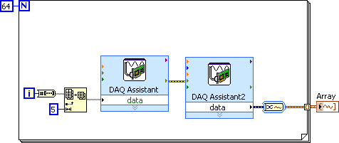
If you had a simple 64 channel mux, the code could be as simple as what is below. The first DAQ Assistant writes a digital value to the mux to select a channel and the second DAQ Assistant reads the output of the mux. The for loop will automatically create a waveform array with 64 elements. You would then index the array to operate on each channel. Since you are using two different muxes, you might want to have two separate for loops. You don't mention how you select between the two different muxes. The actual implementation will depend on which bit you are using for the mux selection. For example, if you were using DO0 through DO4 for channel selection and DO5 for mux selection, you would simply have to add an offset of 32 to the second loop.
Message Edited by Dennis Knutson on 06-19-2007 12:42 PM
