I've seen a number of posts in the forums that are essentially about how to bring real-world signals into Multisim. These posts sometimes generate different possible solutions because there are a few different ways to get real-world signals into simulation. So what are the possible ways and when would you choose each?
LVM/TDM/TDMS data
National Instruments has a few different formats that can be easily generated from LabVIEW measurement equipment. If your data is in one of these formats or you can save data in this format, then you can use the LVM or TDM sources for the data, and these will be by far the easiest approach. You just specify the path to the file (files have the extension .lvm, .tdm, or .tdms), and your data is ready to be used in Multisim.
The sources to use in this case are located at:
Sources > SIGNAL_VOLTAGE_SOURCES > LVM_VOLTAGE
Sources > SIGNAL_VOLTAGE_SOURCES > TDM_VOLTAGE
Sources > SIGNAL_CURRENT_SOURCES > LVM_CURRENT
Sources > SIGNAL_CURRENT_SOURCES > TDM_CURRENT
Time series data
The other common example is if you data is a encoded as a time series. This might be encoded as comma separated values (CSV), tab separate values, or even space separate values. For example, the CSV might look like
0, 1
0.1, 2
0.2, 1
which would give a triangular wave between 1 and 2 volts (or amps) with a period of 0.2 seconds.
In any of these cases, you can use the piecewise sources located at:
The nice thing about these sources is they can accept the data whether it is CSV, tab separated, or space separated, and so they will work for a wide variety of data.
LabVIEW Instruments
A third option would be to create a LabVIEW instrument for Multisim. This is the most powerful and difficult approach, however, it gives you the option of modifying additional customization of the signal, as well as manipulating the signal before it enters simulation. I won't go into the details here because this would be a topic by itself.
That's 3 ways to bring real-world signals into your simulation.
Check out the DevZone for more articles about these sources:
This past week I had the pleasure of meeting some of you during the Multisim Basics course, which runs through the fundamentals of schematic capture and simulation, electronics project management, component creation, design variants and MCU cosimulation.
Two things surprised me: first, the diversity in terms of how Multisim is being used. The attendees spanned education and industry (ranging from military to electronics applications), each having particular requirements for how they needed to use the software. And second, the information I was able to pick up along the way by responding to the various questions that arose.
Some of this information was very specific (for example, the modeling of leakage inductances for a transformer), whereas some was simple GUI functionality that is applicable to everyone. Here are a couple tips for schematic capture in Multisim that I was reminded of while teaching the course.
Tip #1: Continuous Component Placement
In Multisim, the default settings are set so that upon component placement you will be returned to the Select a Component dialog. However, there is also the ability to continously place a particular component.
To configure this setting:
Navigate to Options > Global Preferences
Select the Parts tab
Change Place component mode to Continuous Placement
Tip #2: Specific Schematic Wiring
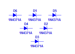
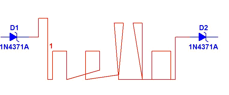
There are times when you may want to wire your circuit very specifically in Multisim. In this case, you can turn off the autowiring feature (which is the default). This will allow you to form multiple segments on your wire. For example, I have wired these two zener diodes together to show you an example.
To configure this setting:
Navigate to Options > Global Preferences
Select the General tab
Deselect the option to Automatically connect components when pins are touching
Questions have come up a few times (1, 2) on the forums about how Multisim handles RLC components. These components are treated a little differently by the software, which is one part of the confusion. So, how exactly are RLC components treated by Multisim? Well, before I explain, I’ll expand on the category. It isn’t just resistors, capacitors and inductors that are a little different. You have to add the electrolytic capacitor, potentiometer, variable capacitor, and variable inductor to the list, but I’ll call them RLC’s for short since the others are really just special types.
Unlike most other components, RLCs are special in that the same functionality is available in a many different packages, with different tolerances, and different instance parameters. In the case of a resistor, the instance parameter is the resistance. The number of combinations is enormous – a search for “resistor” on Digikey showed over 250 000 different through hole and surface mount resistors. In recognition of this variety, Multisim treats RLCs a little differently from other types of components.
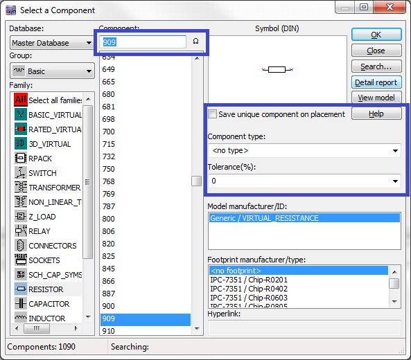
One way to understand how RLCs are different is to answer what does it mean to place a resistor on the schematic, and how is that different from placing another component such as an OpAmp. First off, you get a number of choices. In addition to the footprint, you specify the resistance, the type, and tolerance (the blue boxes). Multisim doesn’t restrict your choice. In Multisim, a resistor is the particular combination of these properties.
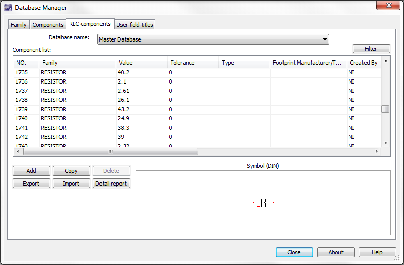
In the component browser, you see a list of common resistance values, and footprints that you can purchase. But where does this list come from, and more importantly can you add to this list? (I'll give a preview - you can add to the list.) But first, you can see this list in Multisim in the Database Manager on the RLC components tab (select Tools > Database > Database Manager).
So there's the list, and if you want to see new definitions in component browser (additional values, type, tolerance, or footprint), you need to edit this list. To add your own definition, click the Add button and create a new definition. Your choices will show in the Place Component dialog. Alternatively, you can check the Save unique component on placement button in the Place Component dialog and Multisim will create the definition automatically for you.
Okay, so this one goes a little further back to Ultiboard 10.1, but I think one release back is still relevant especially for long term users. In 10.1, it became possible to change a via’s lamination after placing the via. You can edit the lamination through the via’s property dialog (just double click the via), or through the Vias tab in the spreadsheet. I added some special information to the spreadsheet to help with editing of vias.
Ultiboard has two types of vias: micro and everything else, which I’ve called standard. The vias look a little different, and in version 10.1 or later, you can use the spreadsheet to identify of the type of the via. You can also use sort on any of the columns, for example, to sort by via type or by lamination.
Ok, it is officially summer in Toronto with the temperature reaching into the 30s (or for those of you who think in Fahrenheit, it has been hovering around 90F)! The heat has really made it too hot to think, but somehow I have put together a new video for you that shows how to import a SPICE netlist in Multisim. The first method is the best, as it supports all models, devices and parameters supported by Multisim's simulation engine, including PSpice parameters; the second is a little more limited as you will see in the video, but useful to generate the schematic of basic netlists.
At approximately 2 minutes and 37 seconds into the video, you will hear some cheering in the background. While I would like to pretend this is an eager audience cheering for my exhilarating display of the transient analysis in Multisim, I must admit that it's actually a group of office coworkers (aka soccer fanatics) cheering for a World Cup match. At times like this, I wonder if the LabVIEW Vuvuzela filter could filter out the cheers of my coworkers as well. Hmm..
Anyway, the Arbitrary SPICE Block is a little-known, but very powerful component that allows the import of a SPICE netlist.
I'm done with hints for a little while; I'm moving on to files. Circuit Design Suite has a number of places where you can specify either a file or a folder in addition to the obvious open and save. These got a few usability improvements in Version 11.0 to make it easier to specify the file and folder. I'm going to use the New PLD Wizard as an example, but these improvements affect more much than just the New PLD Wizard.
Drag and Drop
In Version 11.0, you can now drag and drop files and folders into many places. For example, suppose you are creating a new PLD from a custom configuration file. Normally, you would click the Browse button, and select the file. You can now also drag and drop the file from Windows explorer directly into Multisim. (Sorry, but I don't have a picture for this one - you'll just have to try it for yourself.)
Name Completion
Alternatively, if you know where the file is located on your system, you can now begin typing the path, and Circuit Design Suite will help you to complete the path.
Show on Disk
Lastly, right clicking on paths can now show the path in Windows Explorer. Right now, the way it works is the item is only enabled if the file/directory actually exists, although I did debate this, and feedback on this post could convince me to make this go to the best target if the file/directory doesn't actually exist.
Last time, I wrote about how the spreadsheet now has hints to help identify which cells can be edited, and what will happen when you click to edit the cell. In addition to the spreadsheet, the Results tab in the Spreadsheet View also got some hints in Version 11. Some items in the Results tab have additional information so that you can double click the item, and the item (a net, component, etc) will be highlighted in the workspace. Previously though, it was difficult to identify which items had this "Go to" information, and the best you could do was to right-click on the item and see if the Go to option was enabled.
In Version 11, Go to items are much more common and prominent, thanks to the new schematic capture system, redesigned forward and backwards annotation, and the new programmable logic device feature, all of which are included in Version 11. Like spreadsheets, the Results tab also got some hints. In this case, the arrow icon in the left column of the Results tab (highlighted here in blue) means "I go somewhere."
This post is part of a series on the Importance of Ease-of-Use in Design Tools, which explores how re-thinking graphical capture and simulation can simplify and expedite the design process without sacrificing design capabilities.
Back in university, I had a digital electronics professor who often spoke of the ‘real world' applications of what we were learning, making the lectures both relevant and dynamic. In one particular lecture, he spoke of the use of schematic symbols in digital design and how increasingly, as we progressed in our education, schematics would become simpler by virtue of abstraction (upon abstraction) of the first principles we were learning at that time. This reduction in complexity (for example, the reduction of a complex circuit segment into a simplfied block) makes the schematic easier to read, while at the same time providing the designer with increased efficiency (and ability to innovate) by using high-level blocks.
Considering we were still in the stages of learning simple logic gate design and Karnaugh map minimization, this concept was understandably foreign to us. But as the course progressed, it became clear how these logic gates (which themselves can be considered abstractions) are abstracted away, for example, in the case of a digital adder, or a flip-flop. And we were able to see how, with this abstraction, comes increased power and flexibility through their simplification.
However, recognizing the value of working at this high-level, there may still be times when you want insight into a particular 'block' (or component) in your design. During simulation, for example, this might be to validate a SPICE model, or to simply verify parameters associated with a part. Of course, one option is to investigate the models and parameters associated with each individual component, but this is a tedious method that won't provide you with the holistic view of the SPICE 'code' being simulated.
Check out this video that will give you an idea of how you can get a holistic view of the underlying models and parameters associated with components in your schematic, but still design and innovate at that high-schematic level where it is most efficient. This way you get all the benefits of the abstraction, while still getting insight into those first principles (or in this case, the underlying netlist).
Let me first being with a quick introduction as to what I do at NI, and what I'll be writing about. My name is Garret, the same Garret you may have seen answering your questions on the Circuit Design Suite (Multisim, Ultiboard) forums. I'm one of the software developers for the NI Circuit Design Suite, which means I write the code for the software. As one of the developers, I have a somewhat unique perspective on the software, and through this blog, I'll be sharing some of this perspective. Often that perspective relates to things we've done for ease of use, highlighting little known features, or as Natasha said abstracting away the complexities of traditional electronics design.
For my first post, I'll be talking about a feature implemented in the spreadsheet view that (although subtle) helps designers intuitively understand the function performed by a particular spreadsheet cell. Circuit Design Suite allows for the use of spreadsheets or tables in many areas of the product to display and edit large amounts of information. Everything from the Spreadsheet View to a component's Pin Properties, to the configuration of diode model parameters are displayed using editable spreadsheets. Normally with spreadsheets, it is difficult to tell whether an item is editable, or what will happen when you try to edit the item until you actually try. Everything looks the same.
In Version 11.0, Circuit Design Suite introduced something I’m calling Spreadsheet Hints. These hints are little icons that appear to the right of the spreadsheet cell when you hover over a particular row. Cells that cannot be edited do not have icons. This feature was added as a direct result of a suggestion left on the Circuit Design Suite forums, which we monitor closely for product suggestions and feedback.
So, what are the possible spreadsheet hints and what do they mean? Here's a table that breaks them down:
Icon
Edit behaviour
Description
Text edit
Enter text or numeric information
Dialog box
The item shows a dialog box for complex editing
Drop-down combo box
Select one from a list of items
Check list box
Select zero or more from a list of items
Colour combo box
Select a colour from a list or show the colour selection dialog
P.S. Any requests on "tips-and-tricks" you would like to learn about in the future? Let me know through the comments section below!
Each year, engineers from around the world come to Austin, Texas to attend NI Week (our graphical system design show). It also provides an opportunity for me to catch a flight down to Longhorn land to meet customers, see some amazing keynote addresses as well as give a few presentations myself. As a part of NI Week we also have an Academic Forum which provides an exclusive platform for academic professionals to share their research and teaching methodologies and learn about innovative National Instruments technologies and products used in academia (I stole that from our ni.com/niweek website)
Although I'll be talking a lot about these various events throughout the next few weeks, I am going to begin by announcing to the world that we will be having a:
Panel Discussion on the Future of Engineering Education with Dr. Adel Sedra!
For those of you who don't know who Adel Sedra is - it is likely because you are not an electrical/computer engineer or haven't seen his Microelectronic Circuits textbook. However, as the Dean of Engineering at the University of Waterloo, as well as the fact that his circuits textbook has sold millions of copies around the world, he has become a preeminent leader in Electrical Engineering education. I (along with all my colleagues at National Instruments) am extraordinarily excited to have Dr. Sedra come to NI Week this year for this panel, and he will be joined by Dr. Bill Kaiser (UCLA), Dr. Tony Ambler (UT at Austin), Dr. Jim McClellan (Georgia Tech) and Dr. Delores Etter (SMU) for what we are planning to be a great event at NI Week 2010!
For those of you interested, the panel will take place on Monday August 2nd 2010 at 5pm. Here's a few more details from our website:
Join Dr. Adel Sedra (author of Microelectronics Circuits) and a group of leading circuits and electronics engineering educators to discuss the future of engineering education. This panel will focus upon the current trends and challenges in teaching engineering, as we investigate how to improve the learning experience to inspire the next generation of innovators.
So this is a bit of a different blog entry, because it's actually a user solution in "video form".
I was recently in San Jose for Embedded Systems Conference (I mentioned this a few weeks ago in a previous blog post). While there Ray Rasmussen of iConnect007 asked Nolan Johnson (of Sunstone Circuits) and I to be guest editors for his online magazine. The interview was something I definitely wanted to do as it was with Joe Spinozzi of Cyth Systems. Cyth Systems is a National Instruments integration specialist based out of San Diego, California, with expertise in biotech, aerospace, automotive, electronics, and manufacturing. Joe is great (not to mention passionate - but you'll see this for yourself ), who had joined us at the NI booth to show off the Circaflex™ daughter card system. Getting him on camera to talk about his work was a definite must after just a few minutes of chatting with him.
So what's the story you may be asking? Well, Cyth were looking for ways to create a clean, efficient and robust interface to external systems based on the NI Single-Board RIO platform. They used our NI Multisim and NI Ultiboard circuit design tools to create a daughter card to break out signals to various screw connectors etc… to make development of your domains specific system easier. In the video interview below, Joe gets a chance to speak about his project - why he chose use NI tools (including Multisim and Ultiboard), as well as how Sunstone Circuits were included in his design process to prototype his final board.
A huge thanks to Joe for being such an awesome interviewee!
As engineers, purchasing a design tool is (in general) first and foremost an exercise in reviewing technical specifications versus cost. The tool must a) meet our design needs and b) do so at a reasonable cost. But just as important (and often overlooked) is that the tool (which provides the framework for our final design) must also be easy-to-use and intuitive. Recognizing that an intuitive working environment provides leverage to increase the time-to-market of a design, we see that it is indeed an essential requirement in the purchase of a tool. An intuitive environment allows designers to focus on their expertise (design) instead of wasting valuable time finicking with a poorly thought-out environment.
It's just as Abraham Lincoln famously said, "Give me six hours to chop down a tree, and I will spend the first four hours sharpening the axe". He reconized the power of not just having the right tool, but of having a tool that would facilitate peak performance. And selecting the right tool doesn't mean having the potential to perform a particular function; it's also necessary that it's easy to actualize this function within your design. Owning an overly-complex tool whose features require signifant ramp-up time to use is akin to having unactualized potential - it doesn't take you very far in producing high-quality designs or rapid prototypes.
In the next few blog posts, myself and Garret (a software developer here at NI) would like to to highlight some of the ways that Multisim's graphical simulation environment is able to abstract away the complexities of traditional electronics design, without sacrificing any of the powerful functionality required to enable the production of your designs or prototypes. Although wrapped in a clean and simple interface that doesn't require knowledge of SPICE, advanced users can access more complexity in their tasks on-demand if they are so interesed (and we will show you how!). This ability to work at a higher lever in an intuitive, easy-to-use environment expedites the design process, while still being able to access the lower-level complexity that advanced users would like to tweak.
Perusing YouTube tends to lead me in one of two distinct directions: either towards the pursuit of entertainment (ie. procrastination), or towards the pursuit of education. For example, my last YouTube views have included such gems as this rendition of Bohemian Rhapsody using old-school computer parts, but also more serious material like this refresher on De Morgan's laws.
YouTube is also a rich source of videos on Multisim, ranging from intriguing projects to tutorials on circuit design and simulation. Much of this content is user-generated, but there are increasingly more tutorials being created by the fine folks here at NI. Here's a countdown of my top 10 favorite YouTube videos - both interesting and educational - that in some form involve Multisim or Ultiboard. Prepare for the countdown to Video #1; it is truly inspirational and worth the wait.
Video #10: BCD Decoder to 7 Segment Display with AND, OR & NOT gates
I chose this video to illustrate an important point. To be specific: there are 10 types of people in the world: those who understand binary, and those who don't. Chances are that if you're reading this blog post, that you understand what is meant by this quote, or will likely be learning it very soon. Circuit was simulated using Multisim and then built on a breadboard.
Video #9: Studying Human Locomotion of Amputees Using Prostheses
This is a video of the Intelligent Prosthetic Endoskeletal Component System (iPecs) created by College Park Industries, who used Multisim and Ultiboard to design the circuitry. The iPecs is a wireless research tool that provides accurate measurements to prosthetisists with an accurate picture of how the prosthesis is used in everyday life, to aid in the selection and alignment of components and thereby improve the overall health and well-being of amputees.
Video #8: Class E SSTC 7th Stage Audiomodulated
In my last blog post, I interviewed the designer Tobias Kugeler on his plasma speaker design as shown in this video. The idea is that the sound you hear in the video comes directly from the arc (no speakers are being used, except for the lower frequencies that are being produced by a nearby subwoofer). Multisim was used to simulate the amplitude modulation part of the circuit. To learn more about the design, check out the interview.
Video #7: Circuits Co-Author Michael Maharbiz Discusses NI Multisim
UC Berkeley professor Michael Maharbiz discusses his new textbook, Circuits, which uses Multisim. Learn about how why he wrote the book, and how he uses up-to-date examples, such as the iPhone, to make electronics exciting and relevant to students.
Video #6: Multisim PCM
User PenangSights demonstrates how to run a pulse-code modulation simulation in Multisim and overlays the simulation steps as he runs through his actions in Multisim. He has also created a similar tutorial on amplitude modulation for those interested. Bonus: Funky jazz music keeps things lively!
Video #5 Getting Started with NI Multisim - Analyses - AC Analysis
This tutorial (created by yours truly ) will teach you how to run an AC Analysis using a probe to call out a particular node in your circuit and adding its current or voltage variables to the analysis. If there's a particular video tutorial you are interested in, please post a comment and I will do my best to accomodate your requests.
Video #4: DC Resonance Hydrogen Cell Circuit - Multisim
This user shows us how we can use Multisim to build a DC resonant circuit with the positive DC wave giving off oxygen and the negative DC wave giving off hydrogen.
Video #3: Telephone Number - Final Version
This user has created a circuit that cycles through the digits of his phone number. As a result, I have decided that I will no longer provide my phone number in my email signature to colleagues. Instead I will provide a Multisim circuit file attachment with a similar setup that cycles through my phone number and extension.
Video #2: Rearchitected Forward and Backward Annotation
Are you aware that the forward and backward annotation system has been completely redesigned for Version 11? The new system provides complete transparency of design changes, but allows conflict resolution from directly within the annotation dialog. This video tutorial shows you how to take advantage of this new annotation system.
Video #1: The Colby Chronicles: Fun with Multisim, autism
Colby, a child with Autism, spends over 5 hours a day using Multisim. This video shows the depth of intelligence and focus that these children are capable of, and their passion for learning. Truly inspiring.
A few months ago at DesignCon I got a chance to experience some of the fun of captaining a tradeshow when my marquee demonstration failed to make the trip from Toronto to Santa Clara (all is forgiven, delivery company that will remain unnamed). Since I did not get a chance to show off this awesome content at the Santa Clara Convention Center - I decided to put it into blog form for the rest of the world to see.
The demonstration was created by Application Engineer Fernando Dominguez. Fernando has worked on some great projects including a "Custom Spanish version of NI Multisim" (click here to learn more) so I was excited when he began working on this demonstration. What this does is tie a Multisim simulation into a NI TestStand test sequence. TestStand allows you to automate a number of different test sequences. If you need to go through a number of complex, systematic checks on a product, it can be easily done using automation. Rather than sitting there pressing a button for 20 different tests, they can all be automated with TestStand.
What we have found is that Multisim simulation can play an important role in such a test. Analog and digital designs begin with Multisim, and as such the simulated measurements that are used to verify that the circuit has met specifications before prototyping can also be used as a design benchmark. So by integrating the Multisim simulation results into an automated test sequence you can use these measurements to validate test behavior throughout various sequences. This is a completely new idea, and is very much facilitated by having the ties between Multisim, NI LabVIEW and TestStand (it's the beauty of having test and design software all created by one company ).
Fernando was kind enough to put together a YouTube video of this demonstration. Take a look - it would be great to hear about your thoughts. He does a great job of stepping you through how and what is going on.
Last week I was fortunate enough to return to my alma mater, the University of Waterloo (UW is about an hour outside of Toronto). My main purpose was to meet with Dr. Adel Sedra, who many of you may know from his book "Microelectronics Circuits". He wrote this book (now on it's sixth edition) with Dr. Kenneth C. Smith, and it has become a fundamental book (perhaps even the 'bible') of microelectronics books. We here at National Instruments have a great relationship with Dr. Sedra, and we were fortunate enough to work with him on this latest edition to include the Multisim software, as well as a number of circuit examples with this book. As is befitting meeting a star in the world of electronics education, I got our copy of Microelectronics signed by the man himself (picture below).
For me it was particularly exciting since Dr. Sedra had been my professor for ECE 332 (Electronics Circuits) in the early part of the 2000's (writing this feels like a memoir, and also makes me feel instantly old). Although I may have been known to be late for a few classes, I got to see Dr. Sedra effectively teach pages of the textbook from memory. It was extraordinary how simple he could make topics like MOSFETs to current mirrors sound. Returning to his office as a member of National Instruments to work with him is definitely a fantastic experience.
Speaking to Dr. Sedra is always great, particularly as he speaks to what he envisions as future hurdles in teaching engineering topics. Technology rapidly evolves, and institutions like the University of Waterloo need to keep pace in order to make sure students are turning into tomorrow's innovators. He speaks glowingly about the increased enrollment in programs like Nanotechnology and Mechatronics (programs that had not even been developed when I was at UW). Thinking about these new multidisciplinary engineering programs (electrical + mechanical + systems = Mechatronics), it does provide some insight into how schools are having to keep up with the changing dynamic of the work-force. The domain engineer who is asked to design complex systems by being an engineering "jack-of-all trades" needs to be trained to thing strategically like one. Mechatronics which requires an engineer to touch on everything from robotics, to motors, to circuit design and system-level integration provides the high-level and low-level understanding to develop complex products. Schools like UW are seeing this reflected in their student population.
One last note - there are **rumors** that Dr. Sedra will be heading to NI Week this year in August - so for anyone else looking to get their old Microelectronics book signed by him - make sure you're in Austin the week of August 2nd
I have been the product manager for NI Multisim since 2007, and so it is always exciting when I get to make announcements like this! A few weeks ago at APEX 2010 NI Multisim 11.0 won the PCD&F 2010 New Product Introduction Award for System Modeling and Simulation(wow that's a mouthful). I have been fortunate to have seen the continued evolution of the NI Multisim product-line since the acquisition of Electronics Workbench by National Instruments, and it has culminated this year in this fantastic accolade!
Multisim 11.0 (which was released in January 2010) won the award for it's ability to improve the way in which engineers analyze and improve their circuit designs. Mike Beutow, editor-in-chief of PCD&F commented that “Many of this year’s winners addressed real manufacturing issues, We are thrilled to recognize their creative engineering achievements." Simulation is a powerful tool, and by using it effectively to evaluate design behavior earlier we can reduce errors and improve performance. This was a major motivation for National Instruments to acquire Multisim, and we are seeing industry really grasp this concept.
Considering the years that go into a product launch (from product definition, to development, to final release) it is definitely something I (along with my colleagues here at NI) are hugely proud of! A great deal of our focus over the past few years has been to develop a best-in-class simulation product to help engineers improve the way they design. With features like the LabVIEW Multisim Connectivity Toolkit, completely re-architected SPICE simulation parser, and the continued collaboration with semiconductor companies to get simulation models into Multisim (from Analog Devices, Texas Instruments, OnSemi, Linear Tech, Christophe Basso etc...) I have seen an incredible boost in simulation parser in the product. Engineers and educators have definitely been made happy by all of this!
APEX was held in Las Vegas this year, and I was unfortunately not able to attend (perhaps for the best) - but Vincent Accardi (General Manager up here in NI Toronto) was lucky enough to make it to the desert on behalf of the NI team. He was able to pull out some of his artistic skills to take the picture below of the award set against the backdrop of the Las Vegas Strip - somewhere between New York, New York and the MGM Grande!
So on my latest set of adventures, I made my way to Chicago to attend the annual Project Lead the Way (PLTW) meeting. PLTW is an incredibly innovative organization, which makes working with them awesome! They create technical and scientific curricula that is incorporated at the high school level. High school teachers from around North America become Master Teachers of the PLTW content, and are able to teach students the fundamentals of a number of topics including electrical engineering. Looking at their content, it is amazing what high-school kids are able to learn now. 10 years ago, as I was graduating, I did not have the opportunity to get the leg-up that a program like PLTW provides. I can't wait to see more of the graduates of this program coming through the ranks of the premier engineering schools here in North America (including my alma mater the University of Waterloo).
I was at the PLTW training session to show off some of the great new features of the Programmable Logic Design (PLD) schematic in Multisim. For academic users of Multisim 11.0, you will have begun to see this new feature that allows you to generate raw VHDL directly from Multisim that can be used to program a FPGA (on board the NI Digital Electronics FPGA Board). With this new feature you do not need to simulate a design in Multisim, and then recreate the same schematic in a tool such as that from Xilinx. Instead you can simply use your Multisim representation to program a FPGA. This makes life much easier, as the teacher can focus on educating students on the theory (instead of how to use multiple tools), and the student can get programming much quicker!
The teachers at PLTW were enthusiastic about this new feature, and I can't wait to hear more about their experiences as the new school year begins in September. It was worth the sleepless night from San Jose to Chicago to meet with these Master Teachers last Saturday.
Last week I wrote about the Circuit Design ECOsystem, and how I had attending the Embedded Systems Conference (ESC) to speak to the press about it. What I realized later, is that I had not done a very good job on explaining what exactly the ECOsystem is!
So here I am a week later (back in Toronto on an absolutely stunning day) - making amends for this oversight! I have just finished having a quick lunch in the park, and so am ready to write!
As an engineer embarking upon a new project (regardless of complexity) you will encounter a few fundamental stages. These stages consist of "Part Research", "Schematic Capture", "Design Simulation", "Layout & Routing", "Prototype Fabrication", "PCB Assembly" and "Prototype Validation". You may call these stages something slightly different, but this is what many engineers consider as their design flow.
EDA companies around the world provide products and services that cater to each of these specific steps, however they have unfortunately been developed in a vacuum. Each company has an expertise to meet the needs of the engineer during a specific stage, but not all of them. However nothing has been done to link these services and products together. Once you have finished using a particular tool/application, you are forced as an engineer to ensure your design makes it way to the appropriate stage effectively.A design engineer will touch each of these stages, and EDA companies have simply not made it easy to work through the design flow. Hence something which I call the "brick walls problem". Each stage limits the productivity of the engineer by making it difficult to get to the next step (pictured below).
The ECOsystem which consists of National Instruments, NXP, Sunstone Circuits, Screaming Circuits and Digi-Key takes the expertise of each of these companies in the design flow, and "connects the dots". An engineer can transition to each stage in the design flow more effectively by having a group of companies that knows each others tools, products and services (pictured below). Each company works together to create integrated products, services, and a holistic web experience to make design easier for the customer. So if you are working with National Instruments tools (Multisim and Ultiboard) you can through online integration link to Sunstone Circuits prototype fabrication service to easily get those Gerbers converted to a piece of hardware. By leveraging the relationship with NXP, Digi-Key and Screaming Circuits you can even get that prototype board populated and ready to test with NI hardware!
Speaking to the press about a holistic approach to design, particularly from the perspective of this ECOsystem has definitely been exciting, and as we go forward I can't wait to get feedback from engineers about how this approach helps them get the job done faster! In fact we will have a video interview with our friends at CYTH Systems about just this (it should be live very soon!)
I am currently in sunny San Jose attending the Embedded Systems Conference (ESC). I, along with fellow members of the Circuit Design ECOsystem (Sunstone Circuits, Screaming Circuits, NXP and Digi-Key) were fortunate enough to present on some of our latest innovations with editors from around the US and Canada. Setup adjacent to the San Jose Convention Center at the Hilton, this was my first opportunity to speak to the press about the ECOsystem since September 2009. There had been a similar event in Las Vegas a few weeks ago, but fortunately for me (and my wallet) Vince Accardi (my boss) got to go to that one.
The editors that joined us included - Bruce Bennett (NASA TechBriefs), Russ Pratt (Test and Measurement World), Paul Rako (EDN), Jim Harrison (Electronics Products Magazine), Don Tuite (Electronic Design), Rick Nelson (Test and Measurement World), and Mary Lu Buse (EDN).
Since the Circuit Design ECOsystem began about 2 years ago, we have been working aggressively to complete our vision of a holistic approach to circuit design by leveraging the talents of our respective companies. As I mentioned (perhaps 32 times in less than a hour ) what we are doing is connecting the dots between the various stages of the design flow by working together. It was great to have editors to ask question, provide their feedback and just discuss the vision. One of the most exciting elements of this meeting was that we were presenting testimonials of folks that are using the ECOsystem including one by our good friends from Cyth System in San Diego who have been working on the Circaflex board (a connector system for NI Single-Board RIO). Actually with one of our editors I had the chance to "interview" Joe for a video that should be live on PCB007 within the next few weeks.
I'll be speaking more about this over the next week, as the videos and content start to go live!
For those of you that have spoken with me at a tradeshow or read any of my conversations with editors, you will know that I am quite focussed on the benefits of circuit simulation. It is an easy topic for me to speak to considering I have used the technology in my academic career, and now daily as a Product Manager. It is second nature for me to head to my simulator first when designing a circuit. I may sometimes need a refresher on the theory (I keep a copy of Sedra/Smith's Microelectronics Circuits textbook close by at all times), but I generally can work quickly to a functional circuit.
A vast amount of my time in recent years has been devoted to taking simulation to the next level. "Simulation 2.0" or "Simulation the Next Generation" really revolves around one topic for me - real measurements in the design flow. Simulation is fantastic, but what engineers need is the tools to make results more accurate and to use those results at other stages in the design flow, and it has become clear to me that real measurements can help facilitate this.
I have written countless articles on the topic either for ni.com or magazines, but one of the best documentations of "simulation and real measurements" came from a blog based upon a conversation I had with editor (and master blogger) Paul Rako. Paul and I had crossed paths on many occasions, and it is always great chatting with. He has been tracking the Multisim product-line since it's previous incarnation as Electronics Workbench and continues to be kept in the loop on what we are doing here at National Instruments. In a recent blog entitled "National Instruments Executes on its Simulate-to-Test Strategy" he had same incredible comments and insights on what we are doing here - and I thought I could share a few passages:
Seeing a company with an exciting top-level strategy is a wonderful thing. National Instruments has a brilliant strategy that is focusing on helping engineers. When National Instruments bought Electronics Workbench [Multsim product-line] up in Canada, their brilliance was obvious to me.
I have to admit that when you read an opening to a blog with a line like that - you are definitely a happy Product Manager! Paul continues ...
One thing to note is how well Electronic Workbench [Multisim] does the user interface for SPICE. Rather that insisting that you have a computer science degree and speak geek gibberish, typing the SPICE netlist from memory ... Electronic Workbench got wildly popular in colleges because they decided to have their software speak the language of hardware engineers rather than force us to do geek-speak software talk. So first off, they don’t think of the SPICE net list as the primary thing, they think of the schematic that they derive the net list from as the primary thing. ... I see why college professors love Electronics Workbench. By doing a SPICE simulation, it teaches the kids what test equipment they will be using and where to hook it up ... The brilliant thing about Electronics Workbench is that when you want to do an ac transient simulation, you go to a handy toolbar in the program and drag a spectrum analyzer from the bar onto your schematic. It is a virtual instrument that you plop down on the schematic. When you want to see the bode plot of a node, you just draw wires to the circuit node you are interested in, and then look at the results on the virtual instrument.
Now do you get it? Now do you see why National Instruments’ Dr. Truchard is a genius? He bought Electronics Workbench and yeah, that is great to get NI in the college scene, but the real brilliance is that those little virtual instruments that you drag around in your SPICE simulation can represent real instruments that National Instruments makes....So when you do all the SPICE work up front, you are also defining a test regime for your board. Your real PXI instrument will make a real stimulus just like the virtual stimulus they made in SPICE, and the real PXI instrument will gather results that you can just plop on top of your SPICE results to insure they match up.
Paul truly understands the vision we are working towards here at National Instruments with the integration of simulation and real instruments!
First of all I would like to introduce myself to the NI Circuit Design Community. My name is Natasha Baker, and I am an R&D engineer here at NI for Multisim and Ultiboard, and also an avid participant on the Circuit Design Suite Discussion Forums.
I am always interested in hearing about cool designs created with Multisim and Ultiboard, and part of this involves checking up on the interesting YouTube videos that are being uploaded by our users. Last Friday I was working away here at our Toronto office, when I was pointed to a really neat video of a plasma speaker, which generates sound from sparks instead of speakers (wireless speakers just aren't enough these days). The design was created by Tobias Kugeler from Germany, and simulated using Multisim 11. I was able to catch up with Tobias for a brief Q&A on his design.
Video of the plasma speaker (left) and the Multisim 11 simulation (right)
Designer Name: Tobias Kugeler
Country: Germany
Occupation: Student and Electronics Trainee
Q: Could you tell us a little more about how your design works?
A: The sound you hear in the video comes directly from the arc (no speakers are being used, except for the lower frequencies that are being produced by a nearby subwoofer). The design works like a high-power radio transmitter; it consists of an oscillator with a resonant frequency of approximately 4.35 MHz followed by several amplifiers to get the desired power level at the output.
The fact that you can hear music from the arc is similar to the way a lightning bolt produces sound. The arc has a really high temperature, so the air around it expands. The action of the air expanding and contracting quickly produces soundwaves. Ultimately, this is what produces the sound.
Q: Very cool! How did Multisim play a role in your final design?
A: It was mainly the amplitude modulation part of my circuit that I wanted to improve, but trial and error methods are generally useless. So I looked for a software that could help me out by simulating various circuit setups.
Q: What differentiates Multisim from other simulation products?
A: It is really easy-to-use, and has a lot of electronic devices. I don't know any other program that can handle so many types of devices.
Q: Where did the inspiration for this idea come from?
A: It all started back in 2005. I made some experimental circuits with high voltage devices like flyback transformers, gathering the parts from old televisions. I also read that Plasma speakers were built in the early 80's, so I collected as much information as I could find and started creating schematics. I generated high voltage arcs, and tried to modulate them so they would produce music. I used serveral methods, including frequency and pulse width modulation. But the sound quality back then was not that good (videos from these circuits can be found on my Youtube channel). The original design came from a designer named Richie Burnett who came up with the idea to build a high frequency Telsa coil, so I took his concept and completed it by adding amplitude modultation for audio output.
Q: How, and when did you become interested in circuits/electronics?
A: As far as I can remember, I started experimenting with really simple electronics circuits in 1993. Back then, I never imagined that I would build a Plasma speaker.
Q: Have you made similar designs like this?
A: Well I have built several Plasma Speakers based on different technologies, and using different parts to create the high voltage arc. I built a flyback transformer-based plasma speaker, a solid-state plasma speaker, and a high-frequency Tesla Coil plasma speaker. Every design I have built has been uploaded to my Youtube channel.
Q: How long did the project take?
A: On my high frequency tesla coil, I spent around 15 months of testing. I'm proud that everything works so well now.
Thanks again to Tobias for uploading his design and Multisim simulation on YouTube, and for taking the time to answer my questions.
In the meantime, I am looking forward to hearing from more of our users!
Hopefully for those of you that had a chance to come out to DesignCon last week enjoyed the show. I thought I would share a few thoughts about my time in the Bay area today. First off, National Instruments sent three members of the team to the show: Bhavesh Mistry (Me) - Product Manager, Nestor Sanchez - Product Support Engineer and Vincent Accardi - General Manager. Vincent had fortunately made his way to a candy factory the weekend prior to the show, so were stocked up with Jelly Beans for the duration of the show!
The most important thing to take from DesignCon 2010, was the overall enthusiasm of attendees at this years show. It seems that companies are once more investing in projects and certainly the excitement in engineers as they walked around booths, and investigated new technologies was fantastic. Both Nestor and I had a busy couple of days talking to folks about circuit design, simulation, embedded design and product verification. One thing we both noticed was the movement of companies to more embedded design applications. This provided an opportunity for some crash-courses in LabVIEW FPGA and Single-Board RIO for people walking by our booth. Co-design of analog and digital devices really does seem to be the future of board-level design, and customers seem to have a voracious appetite for those types of "toys" at a show like DesignCon.
Walking around the floor, it was interesting to note that the show had remained approximately the same size since 2009. It is no secret that the "tradeshow" format has seen smaller attendances in North America over the past few years (although Europe and Asia still seem to be doing well!). The exceptions I have noted to this are our own NI Week in August, and now DesignCon. All of the big companies in EDA and test were clearly there, and it seemed that the audience remained engaged with all of us. Our fellow Circuit Design ECOsystem collaborators 'Sunstone Circuits' also attended DesignCon to help support the NI efforts, and throughout the 2 days echoed the overall optimism I am commenting on in this blog.
So wraps up my thoughts about tradeshows for this part of the year. The blog will now get a chance to return to its more standard format of discussing industry trends, best practices and my take on the world of circuit design. I've added a few pictures below to show off our time at the show (and to prove that I didn't spend all of my time in North Beach in San Francisco ).
Till next week,
Bhavesh
P.S. Next week, I will have a video of Applications Engineer Fernando Dominguez demonstrating the Multsim, PXI and TestStand demo he created for DesignCon 2010.
Pictured: Bhavesh Mistry (left) and Nestor Sanchez, Show MVP (right)
Pictured: Multisim user test-drive station, Single-Board RIO and CompactRIO
Pictured: Nestor Sanchez and Vincent Accardi (General Manager - NI Electronics Workbench Group)
Pictured: Fellow Circuit Design ECOsystem collaborators Sunstone Circuits sent along Nolan Johnson and Derrek Morrison
It is the end of January, and we here at National Instruments (well the Toronto office) are preparing for one of our annual trips out to the Bay area. I have to admit that I love making my way down to San Francisco, Santa Clara and San Jose. Driving down roads lined with the names of huge companies like Nvidia, Yahoo and National Semiconductor is a bit of a thrill for an Electrical Engineer. The fact that by next Monday we will likely be basking in the glow of a tablet from Apple (an announcement just hours away), fills me with a little more excitement. Despite all of the various ways I have to communicate with engineers (phone, e-mail, blogs, and even twitter), there is nothing that compares to being face-to-face at a tradeshow. With word coming from all of the various institutions (banks, IMF etc...) that there is optimism for a "stronger" 2010, it will be exciting to see a re-energized group of engineers at DesignCon.
Our theme for DesignCon this year is the 11 Ways to Prototype Faster with NI Multisim. With the recent release of Multisim 11, we have an amazing opportunity to show customers all of the various new features and resources that will make prototyping circuit designs easier. For those of you interested you can follow us on twitter (@multisim) to learn more. Here in Toronto, we have one of our star Application Engineers putting the finishing touches on a brand new demonstration that links circuit simulation and test architecture to make it easier to run multiple simulations (worst case, monte carlo, custom analyses) as well as to streamline the design flow. Seeing him work through the project and develop the various LabVIEW, TestStand and Multisim applications has been great (for those of you not familiar with products like LabVIEW and TestStand - come by our booth at DesignCon to learn more). Along with 10 other demonstrations that we are putting together, it is definitely going to be exciting to see the entire booth come together next week.
Speaking of which ... I can finally speak about our giveaway at DesignCon 2010 this year!
We are making it easier to win this year, and it will all be happening through Twitter! Come by the Multisim booth, and you will be able to:
a.) Start following @Multisim on twitter
b.) Each hour we will then be choosing one of the names of our new followers to win a $10 iTunes gift card [sorry you MUST be attending DesignCon 2010 in Santa Clara to be entered to win]
c.) At the end of Tuesday, February 2nd we will then select one name of our new DesignCon followers (including those that may have won the $10 gift card) for a $100 Best Buy gift card.
It's easy, it's simple, and considering you maybe able to put that money towards a new tablet and eBook reader (still waiting for that announcement Mr. Jobs), we may just have one of my favorite NI give aways yet!
Talk soon!
Bhavesh
P.S. I'll be posting pictures soon for our setup etc...
Towards the end of last year I was contacted by Pete Waddell of UP Media Group (responsible for magazines such as Printed Circuit Design and Fabrication). I have met Pete a number of times, and as we spoke on the phone, he discussed a new article he was writing on the future of the EDA market. My responses (and that of other members of our industry) can be found at http://bit.ly/56kyuw).
Pete did have to truncate some of my answers for the purposes of space. So I thought I could provide some of my responses here in full:
What tool or types of tool(s) need to be improved for today’s’ designs or design process?
For the most part engineers have a wide variety of tools available, each of which focus on a particular niche in the design flow (for which they are fantastic). The problem however, is that the EDA industry has forgotten that the design flow needs to be considered holistically. Schematic capture environments must integrate with simulation, layout, validation, fabrication and manufacturing in order to help streamline the approach of the engineer. Far too often EDA companies focus on just a handful of these stages, and it has resulted in a disjointed and difficult process for the average engineer.
Engineers have the tools that they need for a specific task, but the interoperability of that environment with the rest of the tasks of the design flow need to be improved. As engineers continue to evolve into “domain experts”, responsible for a number of different tasks during the design flow, it becomes ever more important that the EDA industry develop the connective tissue between each stage. Working with NI customers we rapidly found that we need to facilitate that transition from concept, to schematic, to simulation, through to layout, fabrication and validation. Anything hindering the user’s transition to each stage diminishes productivity.
We need to facilitate faster and smarter design [Ed. it looks like Pete used this part of my response for his title ]. We have come a long way as an industry in making tools powerful enough to cope with ever more complex design tasks. However it is not until we look to the design flow holistically, and provide that integrated flow that we truly help improving the productivity of our customers.
Is there an emerging technology that will demand a fundamental change to the design or manufacturing process for PCBs?
There are two separate things that will drive the need for improved design tools.
First, productivity and efficiency will continue to be a major factor in driving the vision for EDA tools and EDA suppliers. This will require continuing to abstract away complexities in the design process, as well as streamlining the design flow through improved integration.
Second, we will continue to see a movement of engineers to embedded technology to deploy the “brains” of their designs. We have seen that in particular, with Field-Programmable Gate Array (FPGA), which have continued to be employed in countless designs. This will continue to move us in the direction of co-design between the embedded device and the PCBs that will help to interface that IC to the real world signals.
Hopefully that helps to provide a little more context to some of our thoughts here on design of PCBs.
Till next time,
Bhavesh
P.S. My interesting fact of the day - the "UP" in UP Media stands for "Uncle Pete". It truly is amazing what you can find out, when attending a tradeshow!
Second ... NI Multisim and NI Ultiboard 11.0 are now available (our 3rd release since 2007). As all of you involved in a product launch know, the months approaching a launch are some of the busiest, and seeing the product ready to be shipped out to customers around the world is one of the most satisfying feelings on earth. Looking across the ni.com/multisim website, I am certainly excited to see how those interested in our products will use the various pieces of technical content we have published. Anyhow (being an engineer) I'd like to describe this launch in numbers:
3: As in the 3rd major release of the Multisim software in as many years
8: Number of new 3-Minute Demo Videos for features in the product (great to check out the new features of the software)
10: "NI Eagle" stress balls thrown at a Product Manager (me) [for various reasons ]
11: As in this is the 11th major release of Multisim (previously known as Electronics Workbench)
15: Number of new whitepapers, tutorials and reference designs published for Multisim 11.0 [note: There are about another 15 articles that will be going live in the next few weeks ]
26: Components for NI mating connectors included in the database
90+: Percentage of PSpice compatibility for Multisim 11.0
550: New components in Multisim from Texas Instruments, Linear Tech and Microchip
650: Updated components in the Multisim database
35,000: Number of hours of R&D development time spent on the product
40,000: Number of cups of coffees digested by R&D/product management (just kidding - sorta)
So for various reasons (including a few listed above), I am definitely excited to get our software out to the students, educators and engineers around the world and see how they take advantage of some very cool new features (like export of raw VHDL straight from the schematic - talk about a time saver!)
Now there is one other number that needs to be discussed:
1: As in the number of blog posts that I have made since September 2009
This is something that will change in 2010 (it's a new years resolution). I will be sequestering myself in a meeting room once a week to make sure that I am blogging on various things circuits related. 2010 marks and interesting year for the EDA industry. After a difficult 12 months in which we saw an incredible slow down in engineering projects there are signs that there may be (conservative) improvements in 2010 (so the economists have been telling us). I hope to see (and comment on) some of this as I make my way to various tradeshows and customer meetings throughout the year.
Actually speaking of tradeshows, I will say that those heading to Santa Clara in a couple of weeks to DesignCon 2010 should definitely stay tuned to learn how you can win prizes from the National Instruments booth!
I’m Bhavesh Mistry, Product Manager for NI Multisim and the newest entrant into the world of blogging (only 5 years late I guess). Over the past year, through my travels, conversations with customers, editors and collaborations with other companies, I have found that there is a lot of information and thoughts out there on the topics of circuit design, circuit education and engineering in general. I’ve been looking for the best way to direct customers and web visitors to this content I have found (including some great resources that I’ve been putting onto ni.com – so I figured this would be a good place to start!
A few questions that I will be answer – before you ask:
a.)Will you only have to read blogs by me?
No! I have many colleagues here at NI that have vast experience in technical topics. I have asked (i.e. forced) them to contribute as much as possible.
b.)Will there be anything interesting on your blog?
I certainly hope so! When not talking about things that I find interesting – like the engineering marketplace, circuits education and the world of tradeshows (I attend them of my free will) – I also hope to point you in the direction of things that are just plain worth reading (dare I say funny as well) A personal favourite of mine is NI engineer Todd at anengineeringmind.com, with videos like the following:
a.)How often do you intend to update your blog?
The Hockey season is just about to start, so I can probably start once the Toronto Maple Leafs are out of contention for the Stanley Cup (so that should be about 3 weeks into October). When I can’t give you something interest myself, I will be ready to point you in the direction of information like that of my good friend Duane Benson at ScreamingCircuits.com, who has been writing blogs a lot longer than me.
b.)Anything else?
Probably lots, but I’ll save them for my next entry.