- Subscribe to RSS Feed
- Mark Topic as New
- Mark Topic as Read
- Float this Topic for Current User
- Bookmark
- Subscribe
- Mute
- Printer Friendly Page
cdaq and encoder -- loosing counts on measurements
11-13-2007 12:49 PM
- Mark as New
- Bookmark
- Subscribe
- Mute
- Subscribe to RSS Feed
- Permalink
- Report to a Moderator
11-13-2007 04:29 PM
- Mark as New
- Bookmark
- Subscribe
- Mute
- Subscribe to RSS Feed
- Permalink
- Report to a Moderator
Hi,
How far are you off from your initial position? Is it off by the same distance or does it vary?
I used an additional DAQ card to generate an encoder signal that generates an equal number of leading/lagging pulses and it counts up from 0 then back down, regardless of how fast I go (tested up to 1 MHz clock rates). I realize I have an ideal test setup though - have you monitored the digital signals to see if they are clean?
I've attached the code I used to generate the test encoder signal (Encoder Test), it's basically just correlated digital output on two lines so you should be able to generate it with an M-Series or another 9401 module in slots 1-4. It has some disabled code so you can see how I generated the output. I've also attached the VI I used to test the encoder signal on the 9401 - it's based off of the "Meas Angular Position-Buffered-Cont-Ext Clk.vi" example. I just used an analog clock for this at 100khz. If you run that code as a feedback test, do you return to 0 or something else? Let me know if you don't have one of those options available, there may be a anotherway to make sure you read the same as I do.
Just to get some details, what rate are you clocking your AI? It shouldn't make a difference for the end value, but it would be good to repeat here. For completeness sakes, what AI module are you using?
If I had to guess now, I would point the finger at the signal not being clean but it's not completely clear yet. If you get screenshots of your signal and/or more details of your settings I'll do my best to repeat your setup and see what is wrong.
Cheers,
Andrew S
11-14-2007 01:47 AM
- Mark as New
- Bookmark
- Subscribe
- Mute
- Subscribe to RSS Feed
- Permalink
- Report to a Moderator
Are you aware that you must connect the second track of your sensor on the second counter of the module to count up and down ?
After that, I agree with stilly32 : there is a example that works fine with a quad encoder.
11-14-2007 08:03 AM
- Mark as New
- Bookmark
- Subscribe
- Mute
- Subscribe to RSS Feed
- Permalink
- Report to a Moderator
11-14-2007 08:29 AM
- Mark as New
- Bookmark
- Subscribe
- Mute
- Subscribe to RSS Feed
- Permalink
- Report to a Moderator
11-29-2007 01:59 PM
- Mark as New
- Bookmark
- Subscribe
- Mute
- Subscribe to RSS Feed
- Permalink
- Report to a Moderator
I'm lookink for your encoder test.vi, but I get only the Lbv 8.2 version! Could you send the same in this version?
Thanks a lot Alain
11-30-2007 12:53 PM - edited 11-30-2007 12:55 PM
- Mark as New
- Bookmark
- Subscribe
- Mute
- Subscribe to RSS Feed
- Permalink
- Report to a Moderator
Message Edited by Mark E on 11-30-2007 12:55 PM
Precision DC Product Support Engineer
National Instruments
12-10-2007 11:36 AM
- Mark as New
- Bookmark
- Subscribe
- Mute
- Subscribe to RSS Feed
- Permalink
- Report to a Moderator
Thanks a lot for your answer, I try your vi on my Cdacq target, a 9172 Cdacq rack with a NI9401 card and différent other cards like digital I/O and analog I/O.
I look like for your vi, because on my application I acquire a encodeur withe the 100Khz Cdacq timebase, but a error -200141 occur my acquisition.This error don't arrive each time, but very offen and need to restart the application. 100Khz is to much for my application, 10Khz or may be 5 will be enough to do it. Bad lock, I can't realize this clock with your vi, I think NI9401 don't accept to work in acquisition in ctro and generation in ctr1 on the same card?
Do you have any experience with this card and this error, I can't find similar problem on the forum for this configuration.
At this time , I turn over?(excuse my english!) this error when I find it, I restart automaticly acquisition, but this solution don't satisfy my customer and me too.
If you need more explication I will return.
Analog I/O is syncrhonize on 9401 PFI0 cadencement source.
Thanks for your help Alain
12-11-2007 07:52 PM - edited 12-11-2007 07:55 PM
- Mark as New
- Bookmark
- Subscribe
- Mute
- Subscribe to RSS Feed
- Permalink
- Report to a Moderator
Hi Alain,
If I understand your problem correctly, you are using your NI 9401 module and the 100 kHz timebase provided by the NI 9172 cDAQ chassis to sample and record the position of an encoder. You are using the previous post’s attached “Measure Linear Position…” example for LabVIEW. However, when you run this example, you sometimes receive error 200141. There are other modules in your 9172 chassis, including an Analog I/O module. Is my understanding correct?
Error -200141 indicates that the position data you are writing to the module’s FIFO is filling the buffer faster than it can be moved to your computer’s RAM and data is being overwritten. Since the 100 kHz sample clock is not a requirement of your application, you can try utilizing another sample clock to fill the FIFO at a slower rate, allowing the data to be moved before it is overwritten and thereby removing this error.
A way to provide this sample clock is to create a mock DAQmx task in LabVIEW that uses a sample clock and then reference that sample clock in your counter task. Since you already have an Analog Input module in your cDAQ chassis, I would suggest creating an AI task. An example of how to modify the block diagram can be seen in the attached screenshot “Add mock AI Task.”
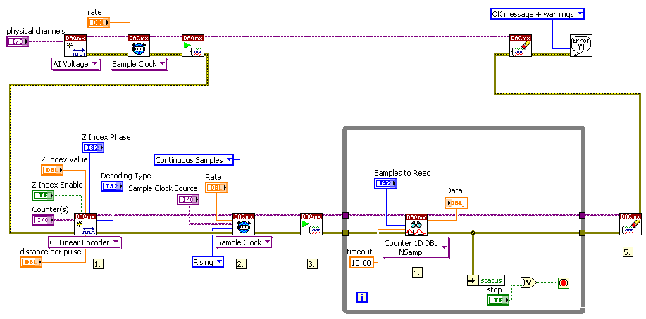
The AI task is configured and started, then cleared after the counter task is complete and no longer needs a sample clock. On the front panel of the example, in the Timing Parameters box, you would select the Analog Input Module’s sample clock as the Sample Clock Source. This can be seen in the attached Screenshot “Timing Parameter Front Panel,” where an AI module was in slot 3.
Good Luck, Mallori M.

Message Edited by mallorim on 12-11-2007 07:55 PM
12-23-2007 05:46 AM
- Mark as New
- Bookmark
- Subscribe
- Mute
- Subscribe to RSS Feed
- Permalink
- Report to a Moderator
